This topic is a reaction to the countless cases of confusion regarding why the bridge “itself” must be listed among tagged or untagged ports of a VLAN in some cases, why the VLAN interfaces must be attached to the “bridge” rather than to its member ports etc. The fact that both “interface” and “port” have multiple meanings in the networking vernacular contributes to that confusion.
This topic does not deal with the details of the “new” way of handling multiple VLANs on a single bridge; for that, a great topic by @pcunite exists.
So, let’s start from a picture of a hardware setup:
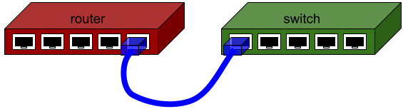
Here, everything is clear – there’s a switch to take care about the L2 forwarding and VLAN filtering, and to one of the physical Ethernet ports of that switch, a router is connected using one of its own physical Ethernet ports.
We can tell the switch which VLANs are permitted on each port or, in another words, which ports are members of each VLAN. Some flavor of the Spanning Tree Protocol may run on the switch to prevent L2 loops caused by wrong wiring. And on advanced models, some filters may control forwarding of frames from the ingress port to the egress one(s).
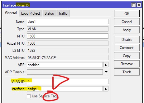
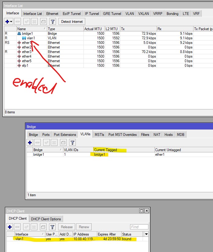
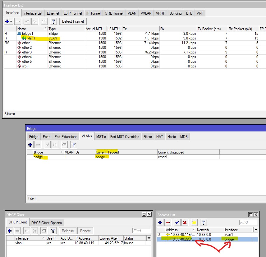
On the router, we can assign an IP address directly to the physical interface; if we want the router to have accesss to multiple VLANs, we could use as many physical interfaces as needed and connect each of them to an access port to that VLAN on the switch, but a better approach is to connect the physical interface of the router to a trunk port of the switch and attach a virtual VLAN interface to the physical one for each VLAN. The virtual VLAN interface picks frames tagged with the right VLAN ID from those that ingress through the physical interface, untags them, and forwards them to the routing engine. In the egress direction, the frames the routing engine sends via this interface get tagged with the right VLAN ID and egress via the physical interface.
We can use a slightly more abstract diagram to represent the same arrangement:
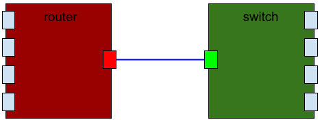
This diagram may still represent the topology shown on the first picture, only the perspective is slightly different. The abstraction allows us to forget about the hardware nature of the functional components and concentrate on their functionality alone. Even if we implement most of it in pure software, the roles of the functional components do not change, i.e. there is still the router whose one interface is connected to one port of the switch, the switch itself, and the other ports of the switch.
Now the software module called “bridge” in RouterOS implements three of the elements above: the switch-facing interface of the router, the router-facing port of the switch, and the switch itself.
The drawing below illustrates that:
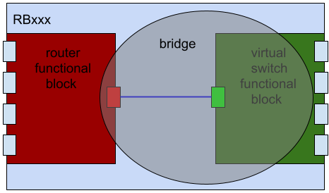
So far pretty clear, isn’t it?
And now the confusing points.
Since, when you add a “bridge”,
- all the three elements (interface of a router, port of a switch, and the switch itself) are created,
- the relationship among the three is a fixed one,
- none of the elements has got any configuration parameter that would overlap with a configuration parameter of the remaining two,
the configuration parameters for all the three elements have been grouped on a single row of the /interface bridge table.
In particular:
- parameters bearing the same names as those on the
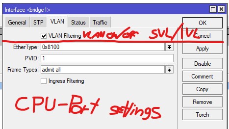
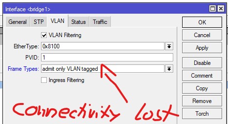
/interface bridge portrows, such as pvid or ingress-filtering, are parameters of the router-facing port of the virtual switch - parameters bearing the same names as those on the
/interface ethernetrows, such as mtu or arp-timeout, are parameters of the switch-facing interface of the router - parameters that don’t fit to any of the two groups above are mostly parameters of the virtual switch; an exception are the admin-mac and auto-mac parameters, which are also parameters of the switch-facing interface of the router.
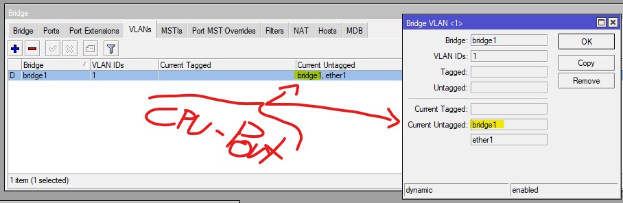
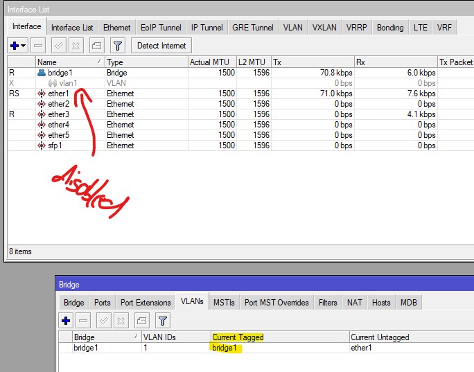
The name item is common for all the three elements. So when specifying the membership of the router-facing port of the switch in VLANs, the same name is used to identify the virtual switch and to identify the router-facing port:
/interface bridge vlan
add bridge=bridge-row-name vlan-ids=10,… tagged=bridge-row-name,…
In the bridge filter, the relationship of the frame to the router-facing port of the switch determines the chain to be used: input handles frames that egress from the virtual switch through that port, output handles frames that ingress to the virtual switch through that port, and forward handles frames that bypass that port.