Map devices with identical IP to external IP based on port

Hello,
I’m working with an embedded system, which has two parts (for the sake of argument, let’s call them parts A and B) which have IP addresses 90.0.0.50 and 90.0.0.51, respectively. Under normal circumstances, these two parts talk only to each other, so it is no big deal if they cannot change their IP.
But, this system can be connected to a PC for debug, reprogramming, etc.
However, I would like to connect TWO of them to one PC, which is a problem considering the identical IP’s. I’ve acquired a Mikrotik router (L009UGiS-RM) so I can resolve this…
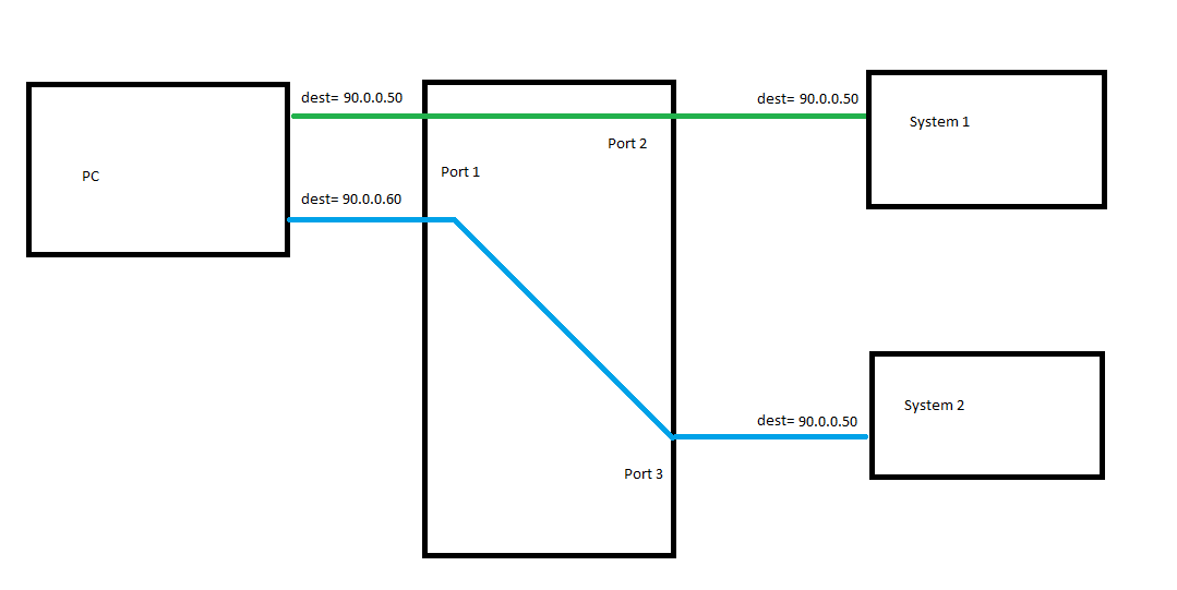
What I want to do, is to map each of the systems to different addresses based on which port they’re connected to. Like this (simplified to only show one of the two addresses):
network_block_diag.png
I’ve seen this topic: http://forum.mikrotik.com/t/connecting-to-multiple-devices-with-same-ip-address/159052/1
which seems to be the same issue, but I’m having trouble understanding what’s going on in the proposed solution:

#add pc-side addresses of router
/ip address
add address=90.0.0.50/24 interface=ether1
add address=90.0.0.60/24 interface=ether1
#add device-side addresses of router
...
add address=192.168.0.1 interface=ether2
add address=192.168.0.1 interface=ether3
...
#mark pakets according to which port they should go to
/ip firewall mangle
add action=mark-connection chain=prerouting dst-address=90.0.0.50 new-connection-mark=port1
add action=mark-connection chain=prerouting dst-address=90.0.0.60 new-connection-mark=port2
...
#transfer the mark from prerouting to routing?
add action=mark-routing chain=prerouting connection-mark=port1 new-routing-mark=port1 passthrough=no
add action=mark-routing chain=prerouting connection-mark=port2 new-routing-mark=port2 passthrough=no
...
#map two PC-side IP's to singular device-side IP
/ip firewall nat
add action=dst-nat chain=netmap dst-address=90.0.0.50 to-addresses=90.0.0.50
add action=dst-nat chain=netmap dst-address=90.0.0.60 to-addresses=90.0.0.50
...
#...?
add action=masquerade chain=srcnat out-interface=ether2
add action=masquerade chain=srcnat out-interface=ether3
...
#????
/ip route
add dst-address=192.168.0.0/24 gateway=ether2 routing-mark=port1
add dst-address=192.168.0.0/24 gateway=ether3 routing-mark=port2

(altered to reflect the addresses I’m working with)

I get what’s going on in most of it, but I’m struggling with the last two sections. What are these doing? And how does the traffic going to .60 and .70 get routed to ports 2 and 3? (if the answerer of that topic was even right at all in the first place, and if it wasn’t, what would be?)

Thank you

By your diagram drawing , I assume you have the following:

  • A pc with two network interfaces ( or a single network interface and you are using Vlans )
  • A switch/hub
  • a system 1 device ( that can not talk to system-2 )
  • a system 2 device ( that can not talk to system-1 )

There are multiple possible ways to do what you are trying to accomplish.

one possible way , can you put secondary IP address on your System-1 and System-2
( example ; system-1 192.168.1.2/24-secondary and system-2 192.168.2.2/24 )
then on your pc , add secondary IPs 192.168.1.1/24 to talk to system-1
and on your pc , add secondary IPs 192.168.2.1/24 to talk to system-2


Another possible way - add two NAT devices where you nat the two interfaces from your system-1 and system-2, then add two port forwards , one for system-1 and one for system-2

Not quite.
-It’s one PC with one network interface. One connection on the PC side; two connections on the device side. The green and blue line represent traffic to/from device 1 and device 2 respectively, which travels over one connection and two addresses on the PC side, but two connections and the same address on the device side.
-As I stated in my post, it’s a Mikrotik L009UGiS-RM router (see https://mikrotik.com/product/l009uigs_rm)
-Yes, system 1 and system 2 shouldn’t be able to talk to each other. Though the main goal is for the PC to be able to talk to them both.

There are multiple possible ways to do what you are trying to accomplish.

one possible way , can you put secondary IP address on your System-1 and System-2
( example ; system-1 192.168.1.2/24-secondary and system-2 192.168.2.2/24 )
then on your pc , add secondary IPs 192.168.1.1/24 to talk to system-1
and on your pc , add secondary IPs 192.168.2.1/24 to talk to system-2

Unfortunately, System 1 and System 2 cannot change anything about their IP addresses (including adding new ones) without a lengthy manual process (think ‘open up the case and flip some DIP switches’, but worse), and then afterward I would have to do it all again to change it all back.
Avoiding this process is the whole point of doing any of this in the first place.

Another possible way - add two NAT devices where you nat the two interfaces from your system-1 and system-2, then add two port forwards , one for system-1 and one for system-2

This is, as I understand it, what I’m working toward, but I’m struggling to understand the approach, as discussed in the original post.

Thank you

Well, you have something wrong in the way you copied the configuration here adapting to your addresses.
The configuration posted by Sob there:
http://forum.mikrotik.com/t/connecting-to-multiple-devices-with-same-ip-address/159052/1
is the “reverse” of the one you just posted, and it uses an approach that is (was) intended for RoS version 6.xx, whilst very likely your L009UGiS-RM runs version 7.xx, and in the latter there are other ways, but for the moment let’s build that configuration.

Let’s call the two devices “targets” and (conceptually and relative to the PC) “WAN” and let’s go backwards.
Since they are system1 and system2, let us connect them to ether1 and ether2, so that numbers match.
Both targets have an IP address of 90.0.0.50, and they are connected respectively to ether1 and ether2, it goes by itself that both interfaces need an address in the 90.0.0.0/24 range, to keep everything with the same number, let’s assign 90.0.0.1/24 to ether 1 and 90.0.0.2/24 to ether2.
The PC will be connected to ether3, using a completely different subnet, so ether3 on the router will have two addresses on that subnet and to keep numbering easier to read, let’s say that they will be 192.168.0.1/24 and 192.168.0.2/24, and the PC itself 192.168.0.3/24.
So, on the WAN side:

/ip address
add address=90.0.0.1/24 interface=ether1
add address=90.0.0.2/24 interface=ether2

And on the LAN side:
/ip address
add address=192.168.0.1 interface=ether3
add address=192.168.0.2 interface=ether3
add address=192.168.0.3 interface=ether3

The third address is useful for accessing the router by IP.

Now the mangle, the marking is done in two stages.

You first give a mark to connections based on their destination address:
/ip firewall mangle
add action=mark-connection chain=prerouting dst-address=192.168.0.1 new-connection-mark=to_target1
add action=mark-connection chain=prerouting dst-address=192.168.0.2 new-connection-mark=to_target2

And then you give a routing mark to them

/ip firewall mangle
add action=mark-routing chain=prerouting connection-mark=to_target1 new-routing-mark=to_target1 passthrough=no
add action=mark-routing chain=prerouting connection-mark=to_target2 new-routing-mark=to_target2 passthrough=no


Now you netmap the two different LAN subnets IPs to the target(s):
/ip firewall nat
add action=dst-nat chain=netmap dst-address=192.168.0.1 to-addresses=90.0.0.50
add action=dst-nat chain=netmap dst-address=192.168.0.2 to-addresses=90.0.0.50

And masquerade/src-nat the WAN side:
/ip firewall nat
add action=masquerade chain=srcnat out-interface=ether1
add action=masquerade chain=srcnat out-interface=ether2

Finally the routing:
/ip route
add dst-address=90.0.0.0/24 gateway=ether1 routing-mark=to_target1
add dst-address=90.0.0.0/24 gateway=ether2 routing-mark=to_target2

On Ros 7 one would use two different routing tables, and possibly routing rules, the approach is slightly different, but once you hopefully get the gist of the above it is relatively easy to “translate” it to the new version.

So to make that work under ROS7 I needed to add:

/routing table
add disabled=no name=to_target1 fib
add disabled=no name=to_target2 fib

before the mangle portion, add:

routing table add fib name=to_target1
routing table add fib name=to_target2

before the ‘ip route’ section, and change

routing-mark

to

routing-table

in the ip-route section.

Which makes this:

/ip address
add address=90.0.0.1 interface=ether1
add address=90.0.0.2 interface=ether2

/ip address
add address=192.168.0.1 interface=ether3
add address=192.168.0.2 interface=ether3
add address=192.168.0.3 interface=ether3


/routing table
add disabled=no name=to_target1 fib
add disabled=no name=to_target2 fib

/ip firewall mangle
add action=mark-connection chain=prerouting dst-address=192.168.0.1 new-connection-mark=to_target1
add action=mark-connection chain=prerouting dst-address=192.168.0.2 new-connection-mark=to_target2

/ip firewall mangle
add action=mark-routing chain=prerouting connection-mark=to_target1 new-routing-mark=to_target1 passthrough=no
add action=mark-routing chain=prerouting connection-mark=to_target2 new-routing-mark=to_target2 passthrough=no


/ip firewall nat
add action=dst-nat chain=netmap dst-address=192.168.0.1 to-addresses=90.0.0.50
add action=dst-nat chain=netmap dst-address=192.168.0.2 to-addresses=90.0.0.50

/ip firewall nat
add action=masquerade chain=srcnat out-interface=ether1
add action=masquerade chain=srcnat out-interface=ether2


routing table add fib name=to_target1
routing table add fib name=to_target2

/ip route
add dst-address=90.0.0.0 gateway=ether1 routing-table=to_target1
add dst-address=90.0.0.0 gateway=ether2 routing-table=to_target2

Though I do have a few things I’m still a little confused about.
First, I noticed you and the example had a ‘/24’ on the end of some of the IPs. What is this? I guessed that this was in reference to an IP port (i.e. port as in port 23 for telnet, not the physical ethernet port) so I removed it in my edit as the devices communicate over several different ports. Though if it’s necessary for some other reason I can add it back.
Second, where does the 90.0.0.0 in the ‘ip route’ section come from? Shouldn’t it need to be 90.0.0.50 since that’s the destination address of device 1 and 2?
In addition, what would I need to add to expand this to address 90.0.0,51 for part B of device 1 and 2?

Thank you

When you say in Mikrotik (example):
192.168.1.1/24

You are saying:
IP address: 192.168.1.1
Netmask: 255.255.255.0 or 24 in CIDR notation

When you are saying:
192.168.1.0/24

You are saying:
Network: 192.168.1.0
Netmask: 255.255.255.0 or 24 in CIDR notation

In some places it may be unneeded, but in most it is needed.

Try running:
/ip address export

then try again after having added to ether4 (only for the example) a few similar addresses:
/ip address
add address=192.168.1.1 interface=ether4
add address=192.168.1.2/24 interface=ether4
add address=192.168.1.3/30 interface=ether4
add address=192.168.1.4/32 interface=ether4

What do you get?

The 90.0.0.0 means the whole 90.0.0.0 network, 90.0.0.0/24 means the network from 90.0.0.0 to 90.0.0.255, in practice usable IP addresses from 90.0.0.1 to 90.0.0.254, you can restrict that to a /30 (four addresses of which two usable) or maybe even a /32 which is a special case, but might work in your setup.

You can play a bit with this:
https://www.calculator.net/ip-subnet-calculator.html
to get familiar with the most common values.