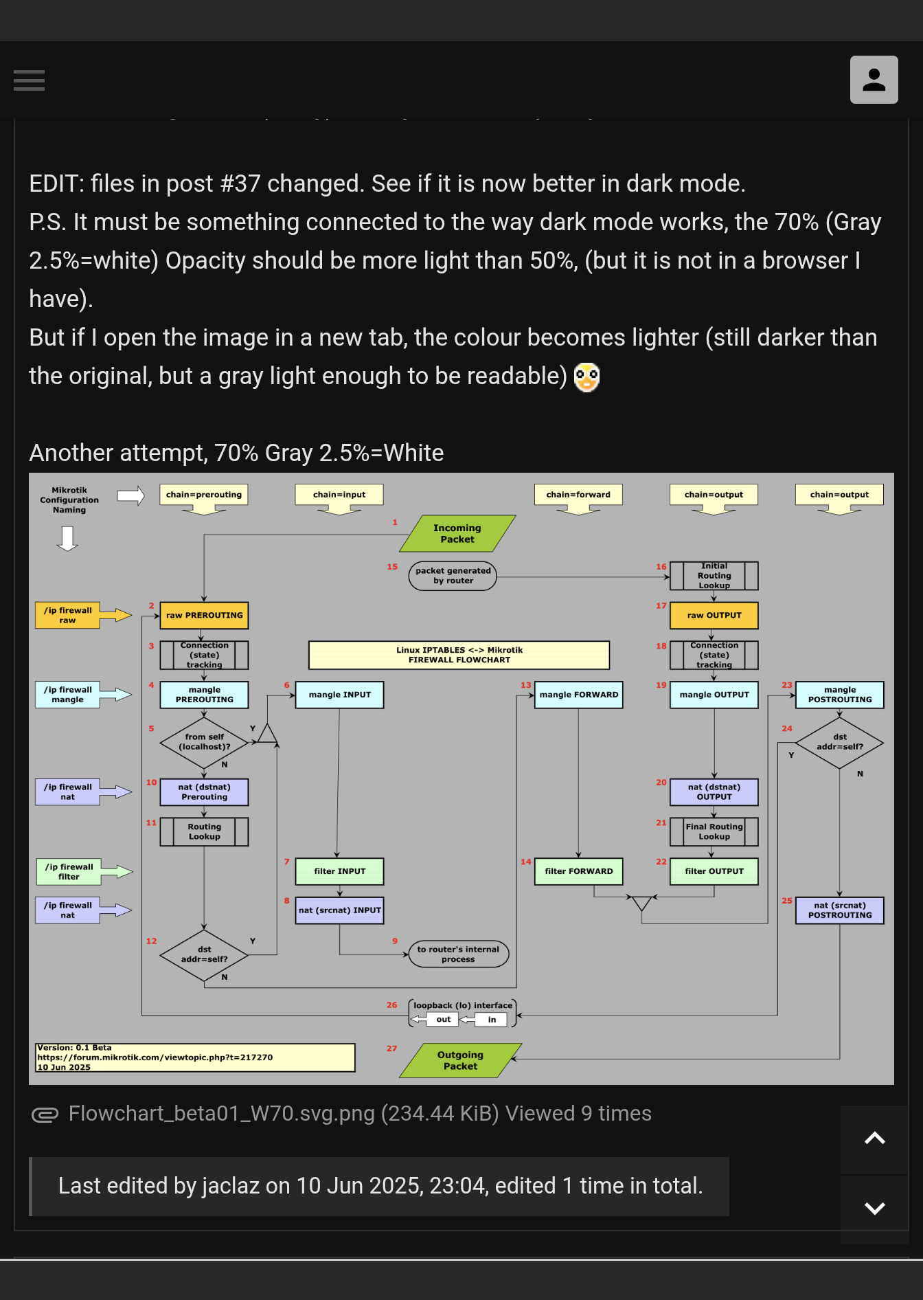
Shouldn’t it say “chain: postrouting” in right top corner?
This version now looks fine on my phone, also good when downloaded as PNG and open with the built-in Windows Photos app👍
(The one that you edited on #37 is however VERY dark)
Try again I re-made the background for the image in post #39.
Should be a very slightly gray white on normal mode and a (rather ugly I have to say, but at least readable) light gray in dark mode.
Still, and still in dark mode if you open the file in a new tab, it becomes much lighter (the shade of gray I actually was looking for not to flash the poor eyes of the poor users of dark mode).
I added a dark mode extension to another PC running Opera (which essentially is (or should be) Chrome to make a couple of tests and when in dark mode the diagram posted by chechito (which is pure white or nearly so) hit my eyes like a flash.
Yep, I’ll fix it.
This version now looks fine on my phone >
> (the one that you edited on #37 is however VERY dark).
Good, probably I had some wrong settings in #37, though if you open the file in #39 on another window, background should become much lighter.
EDIT: OK check these.
The first thing to do when encountering issues is to stop digging! ![]()
Awaiting for the ‘real final product’ to review, litmus test LOL, to see if a half wit can make heads or tails of it.
Really cool to see the collaboration. Imagine if mikrotik enlisted forum talents on some of their ‘godawful’ work.
There is still a few guys in the pic without name. You can add some comments and one will be named anav ![]()
Thanks for the offer, but I dont belong. You guys know what you are talking about from an educated networking and engineering perspective. DYI doesn’t cut the mustard but I am always willing to look at stuff to see if it makes sense for the ‘masses’.
anav could be the one top left, depressed/frustrated as in this thread he cannot suggest VLANs nor “drop all else” as last rule. ![]()
![]()
I don’t know if others agree, but I think that the time to review this and speak up (both approvingly and in disagreement) is about now. I think the structure and naming are about settled - what’s left are typos, rectangle edges that don’t line up just so, background color choices (my suggestion would be already-frustrated-with-mikrotik-push-me-over-the-edge gray - does someone know the RGB for that?)
@jaclaz: The latest version looks really good! Awesome work! ![]()
![]()
![]()
Okay, I will bite.
Lets take the scenario where we mangle traffic coming to the router so it goes back out the same WAN.
Lets say WAN1 is primary and traffic is to the router via WAN2 and needs to go back out WAN2.
/ip firewall mangle
{ mangle for traffic to router }
add action=mangle chain=input connection-mark=no-mark in-interface=lt2p-4g
new-connection-mark=incoming-ISP-B passthrough=yes
+++
add action=mark-routing chain=output connection-mark=incoming-ISP-B
new-routing-mark=to_4gB passthrough=no
I can see via the diagram how the incoming traffic hits Mangle input, but am unable to grasp where this traffic is able to reach mangle output??
I am thinking somehow it SKIPS from step 9 to 15 and then that path?? I see no way it goes to 10,11 and so forth as its directed toward mangle forward and never gets to mangle output ???
@anav: Well then… I’ll bite as well. Actually this is why I asked if it would be useful to outline some common packet flow scenarios - of course, separate from the diagram. (And why I asked that the steps remain numbered ![]() )
)
So let’s look at the case you present. Let’s look at a scenario: you want to reach your router via SSH, both from ISP-A and ISP-B - and of course you want the router to “answer” always on the appropriate WAN connection.
When the external client connects to the router, the packet flow is as follows:
1 → 2 → 3 → 4 → 5 → 10 → 11 → 12 → 6 → 7 → 8 → 9
Let’s say the connection comes in on ISP-B. The only interesting thing to this packet happens in (6) (mangle input) where a connection-mark of incoming-B is assigned to this connection. (If the connection if from ISP-A, no connection-mark is applied.)
When the router answers to the client, the packet flow is as follows:
15 → 16 → 17 → 18 → 19 → 20 → 21 → 22 → 23 → 24 → 25 → 27
The interesting things here happen in the following steps:
(16) Initial routing lookup - this always happens according to the “main” table
(18) Connection (state) tracking - here the connection is recognized as the reciprocal connection to the one added for the incoming packet. The connection’s connection-mark is available from this point on. If the connection came in in ISP-B, the connection-mark is incoming-B, in the connection came in on ISP-A, no connection-mark is present.
(19) Mangle output - here if the connection mark incoming-B is set as per (18), a routing-mark is applied
(21) Final routing lookup - a repeated routing lookup is done, if a routing mark was not applied (the connection came from ISP-A), the lookup is done in the “main” table, if a routing-mark was applied (the connection came in via ISP-B), the repeated lookup in done in the table specified
And everything works out fine. All is joyous.
I saved the short answer for last: you see correctly, no packet goes through both the input and output chains, as none should.
Okay so my guess is that step 9 skips to 15 is correct and that the numbering is not necessarily a traffic flow just a marker number…
Well, not exactly. 1->9 is the flow for the initial packet client->router; 15->27 is for the response packet router->client. They are different packets - that the ssh server (daemon) produced the second packet in direct response to the first is not a firewall question.
E.g. a DNS request may trigger a response, or the DNS server might first contact an upstream, and only upon receiving its answer would it respond to the client, etc. - so it’s entirely dependent on what the given service decides to do.
I (and I’m sure others) would indeed find it helpful to have “common” packet flow scenarios run through the flowchart. This process would be an educational one (to help better understand packet flow and the control thereof within ROS) as well as possibly a check on the the validity and accuracy of the flowchart. I was reluctant to ask/suggest because my scenarios would be of the extremely simple type.
Well, I was only planning on doing simple ones. The one anav proposed here was going to be about the most complicated one I’d go for.
I just think it’s important to understand the “routing adjustment” step, as Mikrotik calls it, and its importance for mangling.
Even if the second (reply/response) packet is not the SAME one, it wouldn’t exist (IF it exists) without the first (incoming) one.
So I think we need to find a graphical way to make it more evident that 9 and 15 are actually (loosely) connected by some mechanisms (which do not belong to firewall and thus it is not shown in detail in the flowchart).
I’ll think of something.
I don’t think that’s necessary (something describing the “link” between #9 & #15), because for a packet destined for the router, its lifetime ended at #9. The “flow” of that packet has finished there.
Let’s say we add something explaining the fact that after a packet has reached #9, some kind of new packet would be originated at #15 in response (even though that’s not true in all case, when a WireGuard handshake packet using the wrong key it sent to the router for instance, absolutely no response packet will be produced), then we would also need to write something explaining that after a packet has been sent to #27, something in response might arrived at #1 (produced by remote devices), or not. But we can agree that this is completely unnecessary and doesn’t need to be mentioned on the flow chart. Which means the possible “link” between #9 and #15 also doesn’t need to be explained neither.
In the old version of the chart, there were the case where the same packet going out of #27 can end up going back to #1 (being the same packet), and that was the router-loopback case, but that specific flow now has its own path through #26 and requires no further footnote/explanation.
@CGGXANNX: I think you put it perfectly! The “explanation” this flow charts shows is that it was transferred to the “local process” - a service, which depending on its exact type and behavior will see to it that it’s processed and will take the appropriate measures. This is full, correct and easily understood.
Actually, this why I think an accompanying “some typical flows explained” document would be nice to augment the understanding around this. But I think this should be a separate thing.
I’m not trying to disparage the efforts in the official Mikrotik wiki, because all those who attempt this sort of thing are bound to fall short in some way, but why their packet flow diagram is often linked to, but I suspect invariably not that useful to those who are referred there, is that they try to cram every case and every complexity into one giant diagram (with sub-diagrams, to boot) and it’s just confusing to sort it all out. Doubly so for people who are not that familiar with the framework - which is most everyone who is referred there. ![]()
P.S. I have a faint feeling that writing these explanations will fall to me. I have a strong inclination to include some examples of encapsulations, because that’s really the case where in some changed form, the packet can actually be viewed as somehow reappearing.
Still, if anav, whom - while maybe not a qualified network engineer - definitely has some little familiarity with Mikrotik firewall settings had this doubt, think of what a newcomer would think/believe..
That the packet is terminated on #9 should be evident by the shape of the box (rectangle with rounded corners means start/end (with respect to the object of the flowchart, i.e. the firewall), but the packet doesn’t go poof, it is actually somehow analyzed/manipulated/changed/transformed/whatever by some mechanism inside the router (router’s internal process).
And I am not going to add an explanation of the mechanisms, only a graphical hint that some mechanism may (or may not) be involved and prompt (or not prompt) the generation of a response packet (packet generated by router).
Anyway, yours and lurker888’s objections are overruled. ![]()
Find attached beta 0.2.
Flowchart_beta_02.zip (15.1 KB)
And yes, I know that today is the 11th, but the idea came before midnight of the 10th, I swear.
To me at least “qualified network engineer” carries not only no weight, but no meaning. What’s the criterion anyway? They have a degree? They’re paid to do it? Most people who have some relevant degree/certification and are paid to do it know way less than @anav. (Quite often so much less, that it’s sad and horrifying.) Okay, rant over.
sobs quietly
But actually your visual representation is nice. I think with the loopback having a strong and definite (thick arrows) flow, the lighter implied coupling between the “to local process” and “generated by local process” actually captures (or rather visually correctly suggests) what’s actually happening. Upon viewing the result, it actually seems intuitively correct.
As a aside: this is why I’m glad to see and happy to participate in your project. We have all grown so accustomed to seeing things shown a certain way and using certain expressions over the years, that it feels natural to continue to use them. But this language (both in the design and text sense) is clearly impenetrable to many, and a set of new eyes is required - which you seem to present with success.