added in a separate .zip a "flat" .svg version.
hopefully the "normal" .svg will render correctly also on machines that do not have Verdana or Jetbrains (or both) installed.
EDIT: Attached a tentative version.
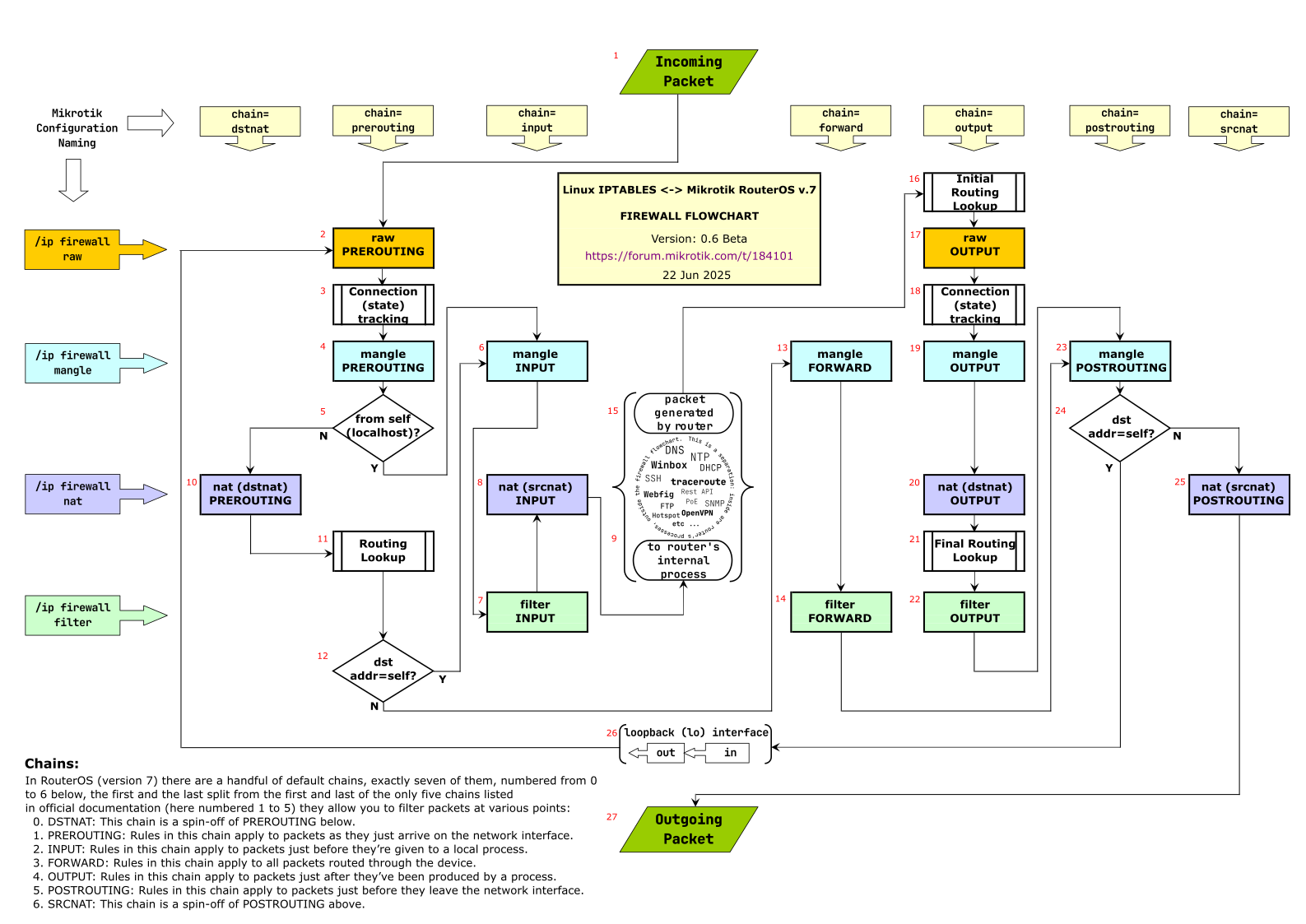
I tried to align boxes along a grid where rows are Mikrotik configuration sections and columns are Mikrotik configuration actions chains.
Needs to be reviewed accurately, as I may well have made some mistake, as i changed the layout or the original.
Numbering remains the same for the moment (it will be eventually removed unless deemed necessary for some reason) even if a few numbered boxes were removed (12,15,and 19).
This is sort of a new take on the usual diagram. I saw some others attempt similar things, but none were really usable - yours actually looks nice. Who knows, maybe it will catch on. Kudos.
The “received by local process” and “emitted by local process” things definitely shouldn’t be left out:
for encapsulations it is often true that the received and emitted packages bear a (mostly) 1:1 relationship and are “some versions” of each other, however they is not the same packet
in many cases for services a sort of 1:1 relationship exists between received and emitted packages, e.g. a DNS request answered, a ping responded to, however these are most definitely not the same packet somehow proceeding though the packet flow
in many cases the router just emits a packet: e.g. doing an IP address update for DDNS (in this case the instigating event is not even related to some other packet, but it’s based on a timer, config change, etc.) or the router wants to make a DNS lookup…
This is just a nitpick, but the triangles to me suggest that there’s something happening there. Maybe it’s just how I visually process things…
EDIT: I would consider retaining some version of numbering or lettering of the processing steps. I often find myself explaining the steps of the packet flow for a particular scenario in writing, and a clear reference would be very helpful in those cases.
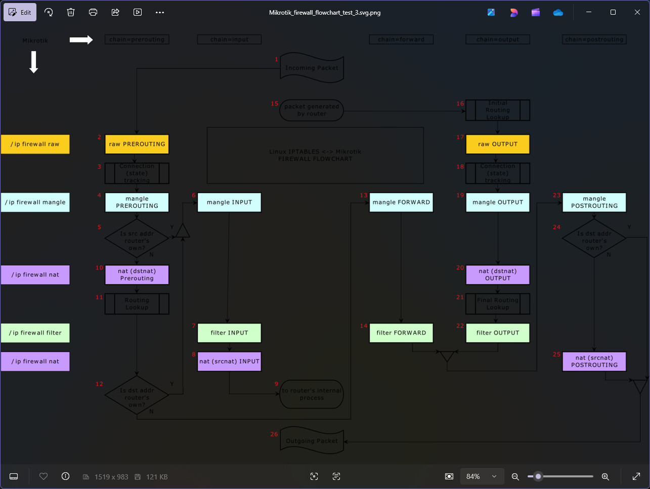
Moved to Excel (which while being a little poorer on the graphic side is easier for managing this kind of stuff, inkscape - possibly my fault - had a couple issues with connectors’ arrows and grid snapping).
Attaching a .png, but this can later become the actual Excel spreadsheet or a pdf.
EDIT: file removed see below
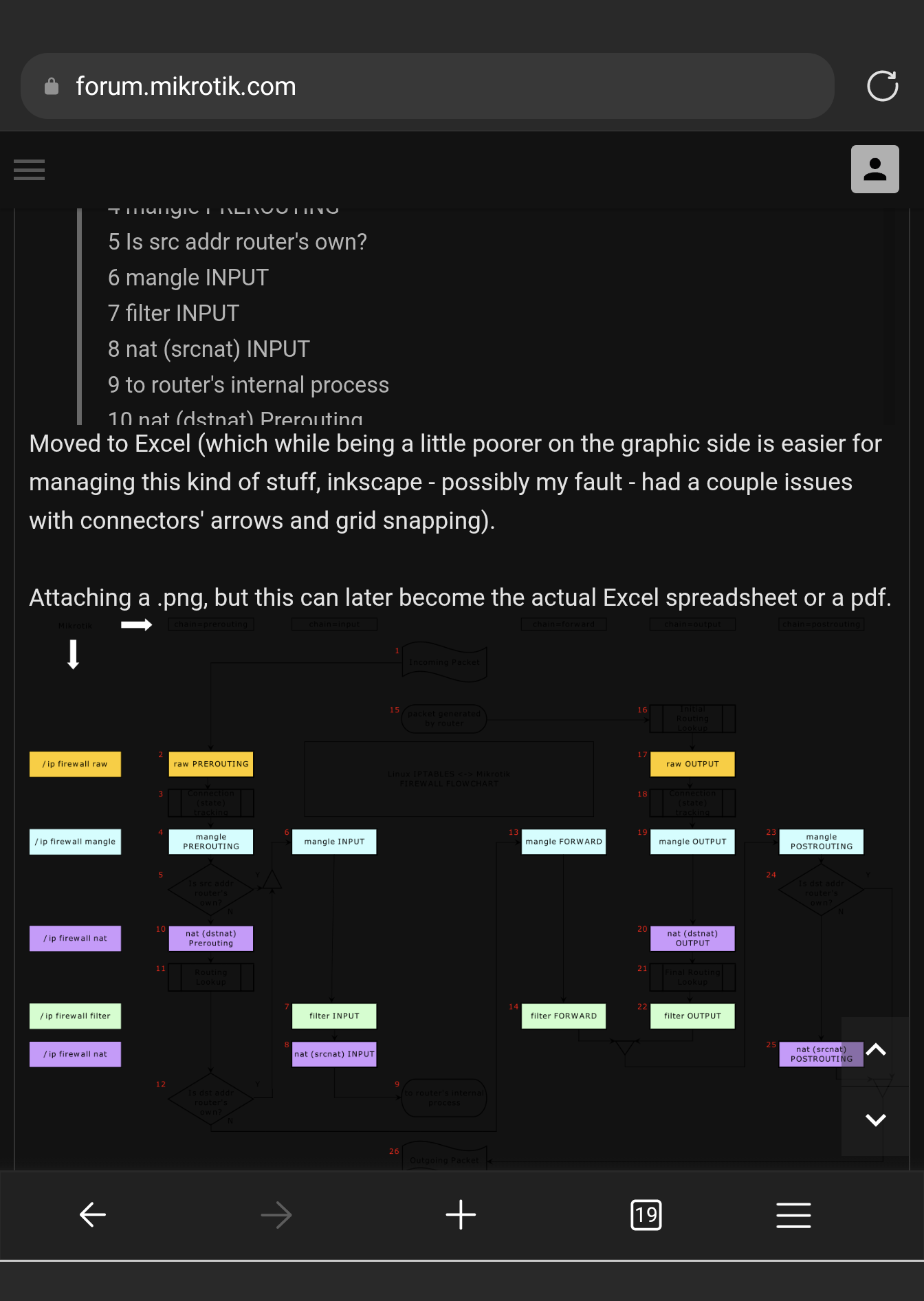
I can’t comment on the flowchart you posted yet because it has the same problems with some diagrams on help.mikrotik.com, that the transparent background makes the image unreadable in dark mode. My phone web browser automatically converts web pages to dark mode (conserves battery with OLED screens) and black lines and texts on deep dark background are invisible.
IMHO it makes little sense to create an image with transparent background while the important details have fixed colors on that same transparent background. Maybe add at least some contrasting outlines or just make the background white/light colored.
This is not simply a problem specific to browsers with automatic dark mode. When, according to plans, this forum switches to Discourse in the near future, the forum software will offer the users the ability to select dark themes too and your flowchart as of now will become unreadable.
EDIT: And it’s also unreadable on my Windows PC in the default Windows Photo Viewer.
I was not aware of #5 and #24 in RouterOS. Does #5 means that if a random device on the network (let’s say on the LAN bridge) sends a packet to the router by faking src-address=192.168.88.1 (assuming that’s one of the router’s addresses) and dst-address=1.2.3.4, dst-port 53, protocol UDP, that packet lands in Mangle Prerouting and then in Filter Input, and then is received by the router’s DNS process, even with dst-address being 1.2.3.4?
Ah I see the #5 and #24 branching box are present on this https://stuffphilwrites.com/fw-ids-iptables-flowchart-v2024-05-22/. However, I think that applies only to locally (on the router) generated packets. That chart has the distinction between “localhost dest” (as well als “localhost src”) and “for this host”. I think “for this host” is what really matches your “Is dst address router own” of #12 but is not for #24.
And it means “Is src addr own’s” should not be equivalent to “localhost src”. From the article, I think it means the packet was generated by the router and destined for the router. And not just any packet with one of the router’s addresses in the src-address field.
In the original article, this was mentioned in the changelog:
2018-09-01: Reflects that > localhost> -sourced/destined packets will not traverse the nat table’s PREROUTING/POSTROUTING chains, respectively. Thanks to commenter Binarus for the pointer.
I am only trying to make the IPTABLES flowchart lurker888 posted a link to at the same time more suited to Mikrotik while keeping it readable by IPTABLES experts AND make it understandable to the “masses” AND attempt to organize it visually in such a way that WHERE the settings are is evident (something that is usually not immediate in most flowcharts I have seen).
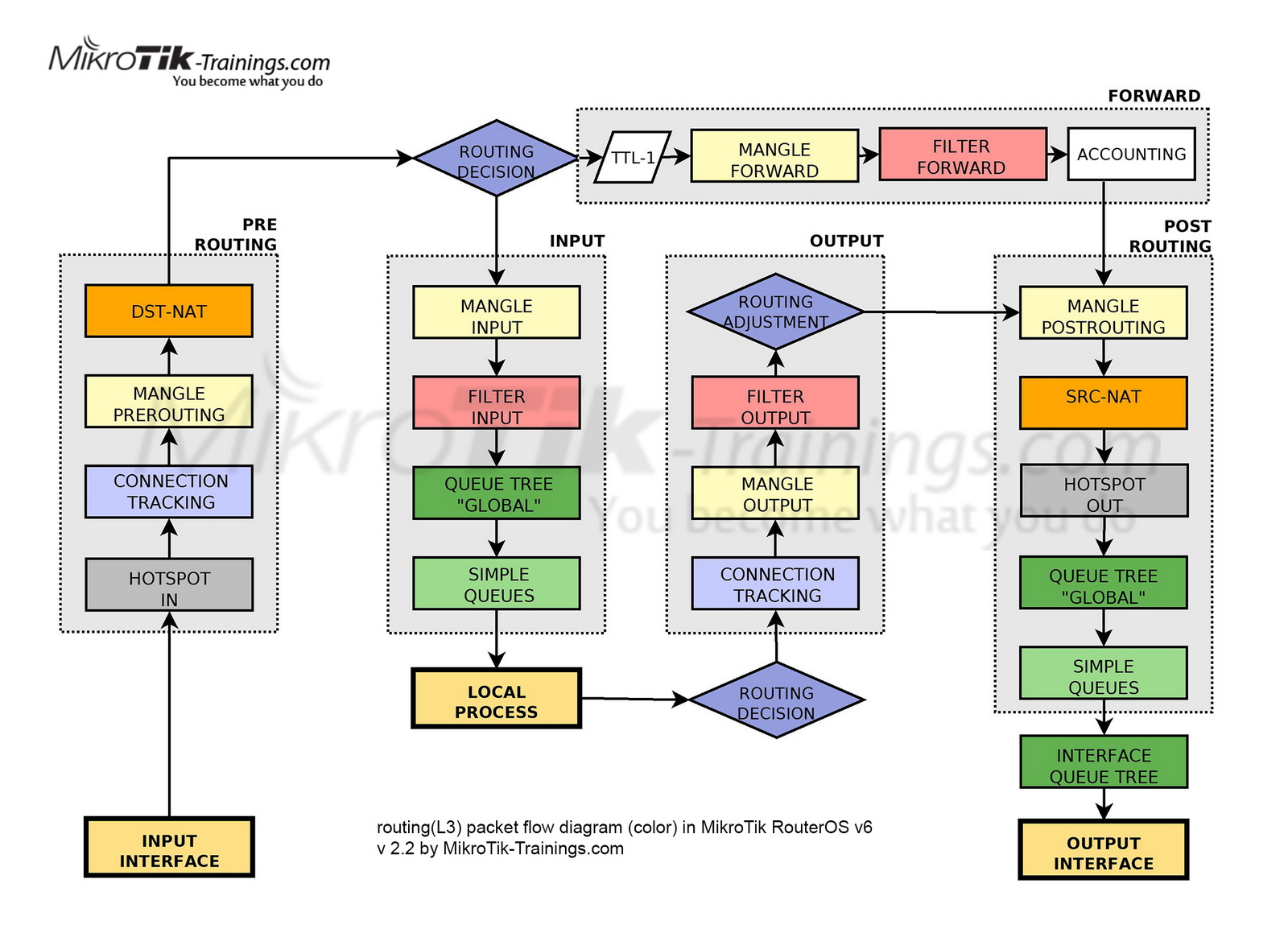
Invariably you are pointed to one (or the other) and told “it is mostly like this BUT …”
My hope is that at the end we can have something that you can point people to and say “it is EXACTLY like this…”
The text of points currently numbered as follows is only an attempt, it can be changed current<- lurker888’s<-original:
5 Is src addr router’s own? ← src addr is router’s addr ← localhost source?
12 Is dst addr router’s own? ← dst addr is router’s addr ← for this host?
24 Is dst addr router’s own? ← dst addr is router’s addr ← localhost dest?
Phil Hagen
September 1, 2018 at 6:32 am
Aha – I see what was meant before and I appreciate the input. I’ve updated this to reflect two differences when handling > localhost-to-localhost > packets. (Note that the nat/POSTROUTING chain is not used for packets destined to localhost either.)
But when you made the change as suggested by others to “match MikroTik terms”, the loopback meaning is lost. Because “Is src addr router’s own?” only mention the source address of the packet and that can be faked by the sender at will.
For #24 is less critical, because the Yes branch of that box can only be taken by packets generated by the router (those that went through the output chain), and will satisfy the “loopback” condition if the Yes branch, even with your wordings, is hit.
Thanks both of you for highlighting this! These cases are why these diagrams are really hard to make: either go into too much detail and lose your audience or be a bit vague or imprecise. I may have gone too far, and we should come up with clearer phrasing: none is clear to me immediately, but I hope we can come up with something.
Let me try to clarify what’s actually happening:
in decision 5, the check is actually: is the ingress interface the loopback
in decision 12, the check is: is the route chosen in 11 a “local” route (more about this later)
in decision 24, the same is true with regard to the last routing lookup performed (for any case where this condition is true, the last routing lookup was made in 21)
About “local”: the linux routing table may contain a flag “local”, as shown in this output produced on a vanilla Ubuntu:
$ ip route list table main
[...]
192.168.80.0/24 dev enp4s0 proto kernel scope link src 192.168.80.229 metric 100
[...]
$ ip route list rable local
[...]
local 172.18.0.1 dev br-6c15e4ab1bf0 proto kernel scope host src 172.18.0.1
[...]
The first “local” in the local table listing signifies the flag deciding this decision.
Maybe “packet from router (itself)” or “packet to router (itself)” would be correct?
EDIT: So to be clear, the case of 5 referd to the ingress interface, while the other two refer to a decision that is indeed made based on the dst addr. (mangling and routing rules may influence this)
I find this better too. And actually the outgoing line from the Yes branch of #24 doesn’t need to go down to #26 and can instead loop up to directly enter #2. This would make the “loopback” explicit.
I think this latter can be solved, I could add a “loopback” box (between 9 and 26) and from it feed it back to 2. That would be something that I would understand much more than either the current go to Outgoing Packet or “direct re-feeding to #2”.
What about the exact text for the decisions (remember that it must fit the diamond/rhombus shape, so not too verbose):
5) …
12) …
24) …
Not saying this is the ultimate, but the decisions could be “from router itself” and “to router itself”
Maybe the loopback situation is best represented by a wavy rectangle (like incoming/outgoing packet") labelled “loopback (lo)” in the center, with an incoming arrow from 24 and an outgoing one to 2? With the arrow leaving 24 to the left it would actually fit ok…
I like the presentation here. While the full detail (other than WG) is in Packet Flow diagrams in docs — those are not very understandable to get the “high level” picture from a “configuration perspective” — so showing the “chains vs /ip/firewall/XXX” is pretty cleaver way to do it. But going into too much detail, any diagram is just going to start looking like MikroTik existing one, so think you’ve capture the right detail here.
I’ve never found MikroTik “local process” a good term, so the “Is src-address router own?” (or similar wording, “<from/to> router itself”) seems more clear than “local process”. And that helps separate out the input/output vs forwarding difference better than mikrotik packet flowIMO.
My only grip be do not use same box for the labels – square boxes are historically a “process”, so the “chain=input” and “/ip firewall raw” should use some other shape. Perhaps grid lines might help, dunno.