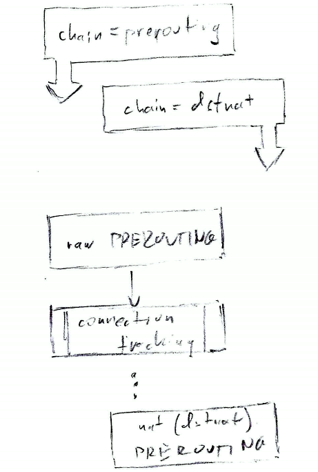
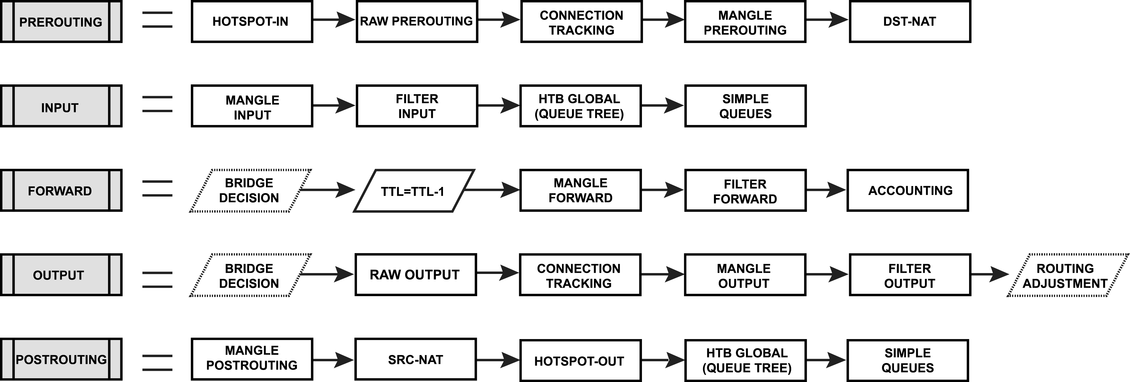
Well, a bit OT, but IPSec is no weirder than WG, just comes with a lot more bells and whistles. WG does spoof checking on the initial handshake where the egress interface gets messed up.
But back to packet flow; both are common denominators for the same reason ie when using “loopback” packet scenarios for the encryption/decryption phase, which needs special clarification.
An alternative, that however, will break the whole meaning of the neatly placed “Mikrotik Configuration Naming” at the top left is:
The top row (the “headers” with the yellow background) are changed to PREROUTING / INPUT / FORWARD / OUTPUT / POSTROUTING
Then the yellow/cyan/purple/green rectangles will have chain=xxx on the 2nd line, for example:
raw \n chain=prerouting
mangle \n chain=prerouting
…
srcnat \n chain=input
…
dstnat \n chain=dstnat
…
mangle \n chain=forward
…
dstnat \n chain=output
…
srcnat \n chain=srcnat
Strictly speaking, the current heading, for example “chain=prerouting” has no meaningful concatenation with “Connection (state) tracking”. Or “chain=output” cannot be put together with “Final Routing Lookup” to form any meaningful phrase. Those headers only “work” when being concatenated on the rows with the colored boxes. But even then, as we have seen, it doesn’t work for #10 and #25.
The Mikrotik syntax in the row/column headings definitely suggests that a valid command can be assembled when reading them in the Y-X direction (the reverse of what you listed.)
And this works! Also for the other boxes (normal non-conntrack ones) as well, including the mustard, arctic blue and mint colored ones. They don’t work only for two of them: #10 and #25.
Something must be done, but I don’t really like either of these:
Abandon the “chain=” in the columns, and put the iptables naming there: “PREROUTING”, “INPUT”, etc., and specify in every box the “chain=prerouting”, “chain=input” syntax. In this way, assembling a Mikrotik command would work along these lines: Read the row label, and append the “chain=” text from the box. Clear enough. (If I understand correctly, this is the solution suggested by CGGXANNX)
Add additional columns for “chain=dstnat” and “chain=srcnat” with the first only having #10 and the second only #25. This isn’t really nice either. Maybe it could be made (at least visually) acceptable by somewhat overlapping “chain=prerouting” and “chain=dstnat”, and offsetting the boxes and labels accordingly, with the same done for postrouting and srcnat. (In this case obviously dstnat would be slightly to the right of prerouting and srcnat slightly to the right of postrouting.)
Maybe the offset chains one (#2) is the less bad? Really don’t know.
(*) - these two are the only ones named different than iptables
Good.
So #10 and #25 are set, they “belong” to /ip firewall nat (and they are purple) and respectively to dstnat and srcnat chains. OK.
Then #8 and #20 ( which right now are purple, indicating that they are in /ip firewall nat, and hold very similar text to #10 and #25) cannot actually “belong” to “/ip firewall nat”, as “/ip firewall nat” has only two chains, srcnat and dstnat.
So, to which section do #8 and #20 “belong”?
Not to /ip firewall nat (per above)
Not to /ip firewall raw, as:
/ip firewall raw has NOT a chain=input
/ip firewall raw has NOT a chain=output
Not to /ip firewall filter.(as just above #8 there is #7 which is actually /ip firewall filter and under #20 there is #22 which is actually /ip firewall filter)
Not to /ip firewall mangle (as above #8 there is #6 which is actually /ip firewall mangle and above #20 there is #19 which is actually /ip firewall mangle)
So, do they actually exist?
And if yes where do we put them?
(and somehow we need to differentiate the text which right now is too similar to #8 and #25)
Haha, now you’re getting the actual depth of the rabbit hole.
The /firewall nat table has chains dstnat, srcnat AND input AND output. And the last two is exactly where #8 and #20 belong.
It’s true that Mikrotik omits the mention of these in its documentation. (I don’t know if that’s absolutely universal, but where I thought to look, it was not there.)
Very good ..
The quick table I posted I extracted from terminal command line of v6.49.17, so something must have been changed in some version of 7.
It will be important to find out which one as the flowchart will apply from that version onwards (and we can make a footnote about chains input and output not being visible in v6 in /ip firewall nat)
Well, I really wasn’t aware that it was ever not available. Again, I use it only on special occasions.
My first guess would have been that if they were added at some point, it would have been when the “raw” table was added, but I think the version you’re referring to already has that…
If no one knows, I’m willing do downgrade one of my spare routers to some previous versions (the one I usually use for testing stuff can be downgraded to 6.40.5). I don’t promise the locate some exact version, but I’m at least willing to take a look at the v7 series.
I think NAT input/output chains are pretty much edge cases, but they definitely have their uses. You might include them in the main diagram, or if you prefer, group them with other, more complex use cases like IPSec and WireGuard encryption loopback in a separate diagram.
Even MikroTik numerous diagrams and text do not seem to cover NAT IN/OUT… Specifically this one (@jaclaz’s “ultimate” is partially a pivot table of it):
(And, when stuff isn’t documented, I generally put in the bucket of things likely not test well either, so not good — here worse, since trying to be definitive about something not documented is problematic at best)
Well, they do work correctly. I mean, they function as they should, and the input validation is fine. I actually use them sometimes.
I can confirm that they’re
already present in 7.1
absent in latest 6.49.18
So it can be declared, that they are a v7 only feature.
EDIT: It would actually be very useful to me personally to have them in the diagram, because the few times I’ve has to use them, I had to then explain in excruciating detail what they are.
More generally, the general idea should be to see further standing on the shoulder of giants.
Depending on Mikrotik documentation (which Is often incomplete, unintelligible, ambiguous, lacking proper examples and sometimes outdated) could be better described as sitting on the laps of dwarves …
It looks great! There are 3 small changes needed, I think:
DHCP should be removed from the process list in the middle. DHCPv4 related packets generated by the router don’t even appear in the output chain, only some incoming DHCPv4 packets are seen by the firewall and the input filter rules have no effects on blocking DHCPv4 client’s request and discovery frames.
Yep, there are a few graphic things to fix, but I won’t do that before all the “relevant” parts (text in boxes, links) are verified and if needed changed.
There is also (for future memory) the down arrow top left that for some reason is not filled white (or the horizontal one that is actually filled) so they look different in the full .png.
About DHCP I understand what you are saying, but DHCP is one of the services/protocols that a common user would recognize, the idea that I want to convey is that “a lot of things” may (or may not) happen once a packet has got to #9 which may (or may not) result in a new or response packet generated by the router in #15.
So, I see as actually good that at least one service listed will do nothing.