Working DLNA routing example (basic)

Hi there. This time I’m trying to understand PIM-SM implementation on Mikrotik device. I post the basic working configuration right here. And for those who is curious, I’ll share more details in the further posts. Hopefully this config would save somebody time. I wasn’t able to directly find answers (those that I would completely understand) in relevant topics and wiki example.

My test lab is following:

  • Qnap NAS – content producer (Prod)
  • Map2nd
  • Windows 10 1803 laptop – content consumer (Cons)

Schema (clickable)

It could happen that with your devices you may need less or more configurations, but nevertheless here’s a working config for the picture above.

/interface bridge
add arp=enabled fast-forward=no name=Cons-Br protocol-mode=none
add arp=enabled fast-forward=no name=Prod-Br protocol-mode=none
/ip pool
add name=dhcp_pool0 ranges=192.168.0.10-192.168.0.20
add name=dhcp_pool2 ranges=192.168.1.10-192.168.1.20
/ip dhcp-server
add address-pool=dhcp_pool0 dhcp-option-set=cons-br-opts disabled=no interface=\
    Cons-Br lease-time=2m name=dhcp1
add address-pool=dhcp_pool2 dhcp-option-set=prod-br-opts disabled=no interface=\
    Prod-Br lease-time=2m name=dhcp2
/interface bridge port
add bridge=Cons-Br hw=no interface=ether1
add bridge=Prod-Br hw=no interface=ether2
/ip address
add address=192.168.0.1/24 interface=Cons-Br network=192.168.0.0
add address=192.168.1.1/24 interface=Prod-Br network=192.168.1.0
/ip dhcp-server network
add address=192.168.0.0/24 dns-none=yes gateway=192.168.0.1 netmask=24
add address=192.168.1.0/24 dns-none=yes gateway=192.168.1.1 netmask=24
/ip firewall address-list
add address=192.168.0.1 list=Bridges
add address=192.168.1.1 list=Bridges
/ip firewall mangle
add action=change-ttl chain=prerouting dst-address-type="" log-prefix=TTL+ \
    new-ttl=set:64 passthrough=yes port=1900 protocol=udp
add action=change-ttl chain=prerouting new-ttl=set:64 passthrough=yes protocol=\
    igmp
/ip upnp
set enabled=yes
/ip upnp interfaces
add interface=Cons-Br type=internal
add interface=Prod-Br type=internal
/routing pim bsr-candidates
add interface=Cons-Br
/routing pim interface
add interface=Cons-Br
add interface=Prod-Br
/routing pim rp
add address=192.168.1.1
/routing pim rp-candidates
add interface=Prod-Br

Don’t forget to add static route on your media server (NAS in my case)

route add -net 224.0.0.0 netmask 240.0.0.0 gw 192.168.1.1 dev eth0

Think about security and limiting mangle rules to the required interfaces only :slight_smile:

Please skip this message if you’re not interested in some kind of TLDR manual.
We start from a scenario where nothing must be done. Map device has 1 bridge with 2 interfaces, DHCP server and that’s it. Just to ensure that there are no problems on the producer and consumer devices.

Schema (clickable)

The config

 
 /interface bridge
add arp=enabled fast-forward=no name=Cons-Br protocol-mode=none
add name=dhcp_pool0 ranges=192.168.0.10-192.168.0.20
/ip dhcp-server
add address-pool=dhcp_pool0 disabled=no interface=Cons-Br lease-time=2m name=dhcp1
/interface bridge port
add bridge=Cons-Br hw=no interface=ether1
add bridge=Cons-Br hw=no interface=ether2
/ip address
add address=192.168.0.1/24 interface=Cons-Br network=192.168.0.0
/ip dhcp-server network
add address=192.168.0.0/24 dns-none=yes gateway=192.168.0.1 netmask=24

As the next step we move ethernet ports into different bridges (clickable).


This is the place where problems start. Devices can ping each other because the other network is available via default gateway. I can open a NAS management page from computer. But the Laptop can’t discover NAS as DLNA server.

/interface bridge
add fast-forward=no name=Cons-Br protocol-mode=none
add fast-forward=no name=Prod-Br protocol-mode=none
/ip pool
add name=dhcp_pool0 ranges=192.168.0.10-192.168.0.20
add name=dhcp_pool2 ranges=192.168.1.10-192.168.1.20
/ip dhcp-server
add address-pool=dhcp_pool0 disabled=no interface=Cons-Br lease-time=2m name=dhcp1
add address-pool=dhcp_pool2 disabled=no interface=Prod-Br lease-time=2m name=dhcp2
/interface bridge port
add bridge=Cons-Br hw=no interface=ether1
add bridge=Prod-Br hw=no interface=ether2
/ip address
add address=192.168.0.1/24 interface=Cons-Br network=192.168.0.0
add address=192.168.1.1/24 interface=Prod-Br network=192.168.1.0
/ip dhcp-server network
add address=192.168.0.0/24 dns-none=yes gateway=192.168.0.1 netmask=24
add address=192.168.1.0/24 dns-none=yes gateway=192.168.1.1 netmask=24

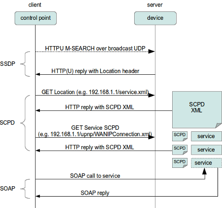
If I understood properly it is SSDP that is responsible for the discovery. Packets are always sent to UDP port 1900, but the source port may vary. There are many posts saying that SSDP packets have TTL=1 thus those are not forwarded anywhere. Ok, I think we can fix that with a mangle rule:

/ip firewall mangle
add action=change-ttl chain=prerouting disabled=yes dst-address-type=multicast \
    log-prefix=TTL+ new-ttl=set:64 passthrough=yes port=1900 protocol=udp

Note that according to specification packets have to be sent with TTL=4, although some devices ignore that. I’m not sure whether higher TTL may cause issues, at least it doesn’t with my setup.

Then we need to configure PIM to ensure multicast packets are routed between bridges. Here comes the tough part. In the PIM example it says that it’s enough to add bridges into PIM interfaces and configure a static Rendezvous Point (RP). We do not need to add any alternative addresses because devices can easily reach each other. From Wiki:

You may also need to configure > alternative-subnets > on upstream interface - in case if the multicast sender address is in an IP subnet that is not directly reachable from the local router

The RP is recommended to be a place closer to a Producer, because the traffic is sent from Media server down to all devices that are subscribed to certain groups. In my case I use Br-Prod 192.168.1.1 as RP. I’m not sure whether Bsr has to be defined, I haven’t yet understood its purpose.

 
 /routing pim bsr-candidates
add interface=Cons-Br
/routing pim interface
add interface=Cons-Br
add interface=Prod-Br
/routing pim rp
add address=192.168.1.1
/routing pim rp-candidates
add interface=Prod-Br

Additional thing that is mentioned to add a static route on the Producer. DLNA uses 239.255.255.250 group. Otherwise we can specify all default multicast groups 224.0.0.0/4 so I added route to this network via IP address of the Bridge where Nas is connected. Command is executed on the Nas:

 
route add -net 224.0.0.0 netmask 240.0.0.0 gw 192.168.1.1 dev eth0

New route is added. Be aware that this route would exist until reboot. Check this page to see how to do it permanently using autorun script.

 
route -n
Kernel IP routing table
Destination	Gateway		Genmask		Flags Metric Ref    Use Iface
0.0.0.0		192.168.1.1	0.0.0.0		UG	0      0        0 eth0
127.0.0.0		0.0.0.0		255.0.0.0	U	0      0        0 lo
169.254.0.0	0.0.0.0		255.255.0.0	U	0      0        0 qvs0
192.168.1.0	0.0.0.0		255.255.255.0	U	0      0        0 eth0
224.0.0.0		192.168.1.1	240.0.0.0	UG	0      0        0 eth0

Now I need to ensure that both NAS and Laptop are sending SSDP packets to router. Add following rules. The first one would show that SSDP packet arrived the bridge interface, the second one shows packets that are forwarded between bridges.

 /ip firewall filter
add action=passthrough chain=input dst-address-type=multicast dst-port=1900 \
    log=yes log-prefix=in-SSDP protocol=udp
add action=passthrough chain=forward dst-address-type=multicast log=yes \
    log-prefix=fw-SSDP port=1900 protocol=udp

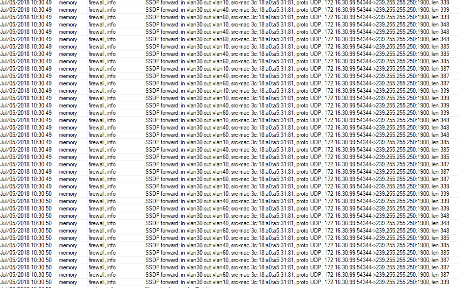
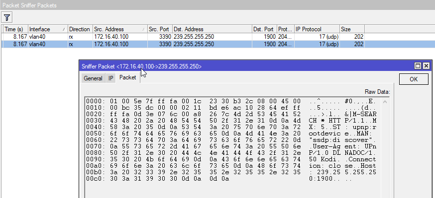
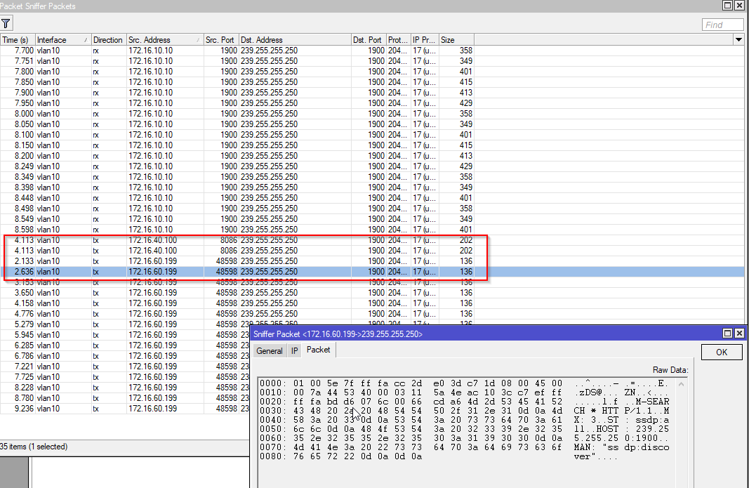
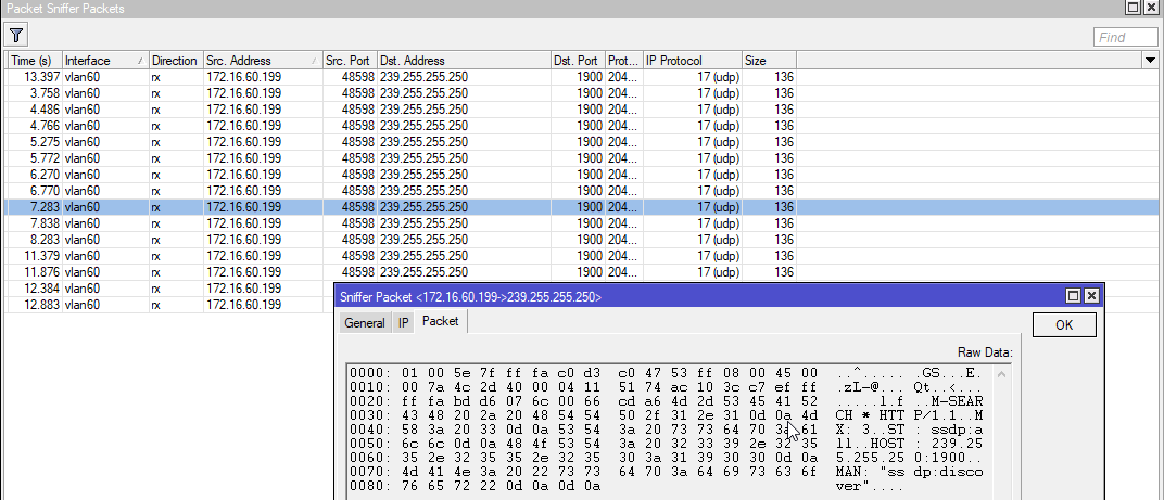
So far so good, counters are changing, log shows that packets arrive and forward. I can see SSDP from Laptop that is sent to both bridges. The ones from laptop have smaller size, the others from Nas are bigger (clickable).


PIM results are following and look valid to my understanding.

 
 /routing pim> bsr print 
 zone-type=active bsr-address=192.168.0.1 scope-zone=224.0.0.0/4 bsr-priority=1 
   local-address=192.168.0.1 local-priority=1 state=elected timeout=31s 

 zone-type=configured bsr-address=192.168.0.1 scope-zone=224.0.0.0/4 
   bsr-priority=1 local-address=192.168.0.1 local-priority=1 state=init

/routing pim> mrib print 
Flags: X - disabled, I - inactive, D - dynamic 
 #   DESTINATION        GATEWAY         METRIC INTERFACE                         
 0 D 192.168.0.0/24     0.0.0.0              0 Cons-Br                           
 1 D 192.168.1.0/24     0.0.0.0              0 Prod-Br   

/routing pim> mfc print 
GROUP           SOURCE          RP             
239.192.152.143 192.168.1.18    192.168.1.1    
239.255.255.250 192.168.0.18    192.168.1.1    
239.255.255.250 192.168.1.18    192.168.1.1    

/routing pim> join print 
Flags: RP - (*,*,RP), WC - (*,G), SG - (S,G), SG_rpt - (S,G,rpt) 
       GROUP           SOURCE          RP             
    WC 224.0.0.0       192.168.1.1     192.168.1.1    
    SG 239.192.152.143 0.0.0.0         192.168.1.1    
    SG 239.255.255.250 0.0.0.0         192.168.1.1    
SG_rpt 239.192.152.143 192.168.1.18    192.168.1.1    
SG_rpt 239.255.255.250 192.168.0.18    192.168.1.1    
SG_rpt 239.255.255.250 192.168.1.18    192.168.1.1    

/routing pim> igmp-group print 
Flags: v1 - IGMPv1, v2 - IGMPv2, v3 - IGMPv3, 
I - include, E - exclude, F - forward, D - don't forward 
    INTERFACE                GROUP           SOURCE          TIMEOUT             
v2E Cons-Br                  224.0.0.2       0.0.0.0         3m44s               
v2E Cons-Br                  224.0.0.13      0.0.0.0         3m49s               
v2E Cons-Br                  224.0.0.22      0.0.0.0         3m45s               
v2E Cons-Br                  239.255.255.250 0.0.0.0         3m46s               
v2E Prod-Br                  224.0.0.2       0.0.0.0         3m55s               
v2E Prod-Br                  224.0.0.13      0.0.0.0         3m47s               
v2E Prod-Br                  224.0.0.22      0.0.0.0         3m48s               
v2E Prod-Br                  239.192.152.143 0.0.0.0         3m51s               
v2E Prod-Br                  239.255.255.250 0.0.0.0         3m48s

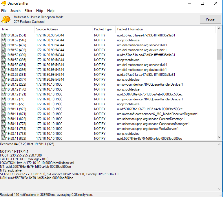
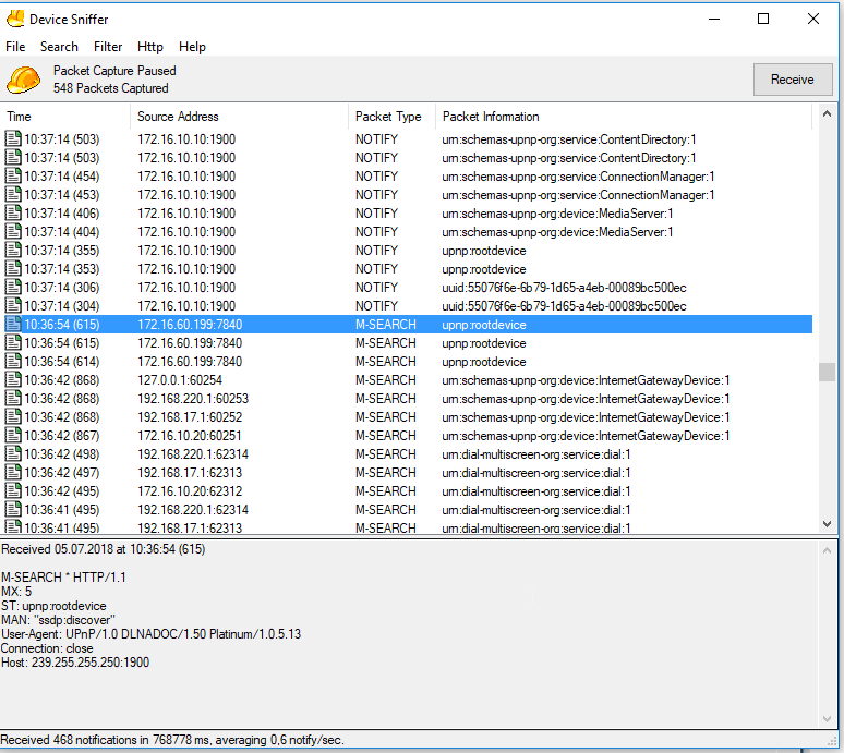
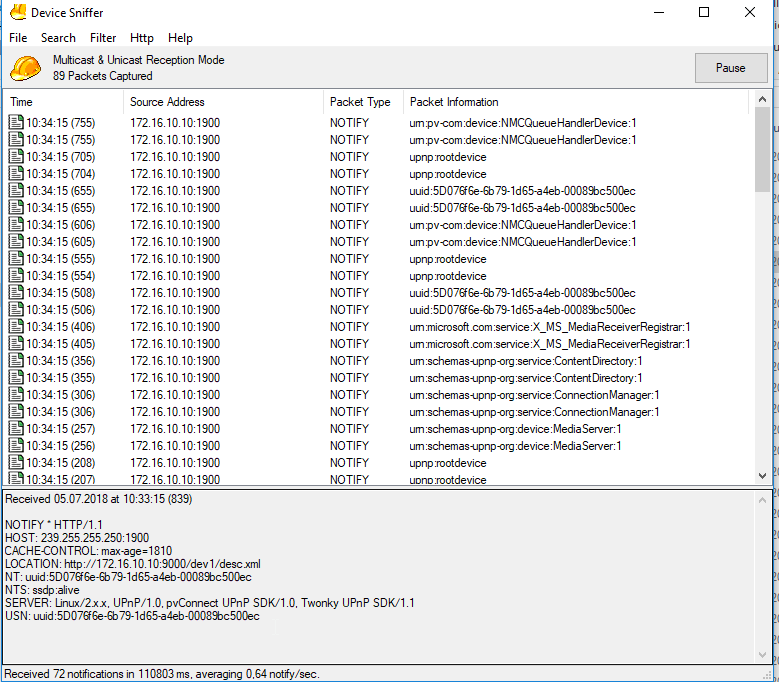
But the whole setup doesn’t seem to be working. Device Sniffer tool from Developer Tools for UPnP Technology allows me to check what messages does my Laptop see. The only reasonable NOTIFY message with ssdp:alive from Nas (although those are very rare). Thus something seems to be working according to UPnP documentation. The thing is packet arrives with NT header, meaning that it is NAS who informs network about his presence. A response to M-Search should have been arrived with ST header inside NOTIFY packet.


This issue leads me to the conclusion that other bridge doesn’t receive some IGMP packets. First things first, just like with SSDP TTL, add mangle rule that would increase TTL for IGMP traffic.

 
 chain=prerouting action=change-ttl new-ttl=set:64 passthrough=yes 
      protocol=igmp log=no log-prefix=""

And right after that everything starts to work properly.

Improvements
Distribute static multicast routes to the networks where you suppose to have media servers. Thus, you don’t need to add routes manually. This can be done using DHCP option 121 and the following helper.

 
 /ip dhcp-server option
add code=121 name=cons-mcast-routes value=0x04e0c0a80001
add code=121 name=prod-mcast-routes value=0x04e0c0a80101
/ip dhcp-server option sets
add name=cons-br-opts options=cons-mcast-routes
add name=prod-br-opts options=prod-mcast-routes

/ip dhcp-server
set [find interface=Cons-Br] dhcp-option-set=cons-br-opts  
set [find interface=Prod-Br] dhcp-option-set=prod-br-opts

My Qnap doesn’t understand this option unfortunately, so I add it manually as shown previously. It’s worth to mention that some devices require option 249 to receive routes properly. It’s not my case, but you can easily find more information.

One more hint. One of my computers couldn’t see NAS until I changed proxy mode on bridges from enabled to proxy-arp.

Thank you for reading.

Hi everybody,
I found this thread, because I struggle a little bit with the same issue. Maybe someone can help me with this specific setup, because I’m a little overwhelmed with the stuff.

I have a Twonky- DLNA-Server running on a qnap in VLAN10. The clients (e.g. Samsung TV) is in VLAN40.. Both VLANs are on the same Bridge with vlan-filtering. The environment works if both devices are in the same vlan-subnet.

I´ve installed PIM and have added the interfaces VLAN10 (172.16.10.0/24) and VLAN40 (172.16.40.0/24) but nothings happens.
What is necessary in addirion to make the Twonky DLNA-Server on VLAN40 visible?

Thanks in advanced,
Christian

Hi, what does following command say?

/routing pim mfc print detail

There should be an entry with following values:

  • proper group (I suppose it should be 239.255.255.250)
  • VLAN10 as upstream interface
  • VLAN40 as downstream interface

Do you have an RP defined? Can you see your devices IPs joined that RP in

/routing pim join print

Do you have firewall rules? Do they allow multicast traffic?

You can use Device Sniffer as shown above to see whether you receive Upnp packets in both VLANs.

I run similar setup to yours, except my one PIM interface is VLAN and the other one is bridge with VPN interface. And I can receive DLNA over VPN connection properly.

Hi Chiverel,
thanks for your quick response!

I use PIM also for my Sonos Network, and it works The Players are on vlan30, controller on vlan10 and vlan60 (but seems to be not necessary in PIM)

Here is the log:

 /routing pim mfc print detail
 group=239.255.255.250 source=172.16.10.10 rp=172.16.30.1 upstream-interface=vlan10 downstream-interfaces=vlan30,vlan40 
 group=239.255.255.250 source=172.16.10.20 rp=172.16.30.1 upstream-interface=vlan10 downstream-interfaces=vlan30,vlan40 
 group=239.255.255.250 source=172.16.30.11 rp=172.16.30.1 upstream-interface=vlan30 downstream-interfaces=vlan10,vlan40 
 group=239.255.255.250 source=172.16.30.34 rp=172.16.30.1 upstream-interface=vlan30 downstream-interfaces=vlan10,vlan40 
 group=239.255.255.250 source=172.16.30.36 rp=172.16.30.1 upstream-interface=vlan30 downstream-interfaces=vlan10,vlan40 
#### 
 /routing pim join print
Flags: RP - (*,*,RP), WC - (*,G), SG - (S,G), SG_rpt - (S,G,rpt) 
       GROUP           SOURCE          RP             
    WC 224.0.0.0       172.16.30.1     172.16.30.1    
    WC 224.0.0.0       172.16.40.1     172.16.40.1    
    SG 224.0.1.60      0.0.0.0         172.16.40.1    
    SG 239.255.255.246 0.0.0.0         172.16.40.1    
    SG 239.255.255.250 0.0.0.0         172.16.30.1    
SG_rpt 239.255.255.250 172.16.10.10    172.16.30.1    
SG_rpt 239.255.255.250 172.16.10.20    172.16.30.1    
SG_rpt 239.255.255.250 172.16.30.10    172.16.30.1    
SG_rpt 239.255.255.250 172.16.30.11    172.16.30.1    
SG_rpt 239.255.255.250 172.16.30.34    172.16.30.1    
SG_rpt 239.255.255.250 172.16.30.36    172.16.30.1

Interface-Lists:

/interface list member add interface=vlan10 list="Sonos Control" comment=SONOS
/interface list member add interface=vlan60 list="Sonos Control" comment=SONOS

FW Rule implemented for Sonos:

/ip firewall filter add action=accept chain=forward dst-address=239.255.255.250 comment="SONOS: forward Multicast traffic"
/ip firewall filter add action=accept chain=forward dst-port=1400,4444,4070 in-interface-list="Sonos Control" out-interface=vlan30 protocol=tcp comment="SONOS: forward  Controller events to Players"
/ip firewall filter add action=accept chain=forward dst-port=3400,3401,3500,4070 in-interface=vlan30 out-interface-list="Sonos Control" protocol=tcp comment="SONOS: Forward Contoller events  from Players"
/ip firewall filter add action=accept chain=forward dst-port=1900,1901,5353,6969 in-interface=vlan30 out-interface-list="Sonos Control" protocol=udp  comment="SONOS. Forward UPnP Device Discovery events from Players"

Regarding Device sniffer:

I am not sure how to start this, but thi seems to be that I have to enable upnp on RB3011, or what do you mean?
sorry for my stupid questions, but I am not a big expert here :wink:
Thanks so much,
Christian

I’m not a specialist as well. But have been investigating PIM a bit.

I do see that you have 2 RPs configured. I assume that in your setup there should be only 1 RP which is 172.16.30.1. Could you post your

/routing pim export

In addition you need to allow SSDP traffic from your VLAN40 similar to what you did for VLAN30. I do believe that DLNA uses at least SSDP udp/1900 for the discovery purposes. Thus that traffic should be able to reach your VLAN40 interface (172.16.40.1 I suppose).

Regarding the device sniffer. You need to download that tool, run it on some PC/VM/whatever and have that host connected to your VLAN40. This way you can check what Upnp messages appear in this network. Then use the same approach on your VLAN30. You can initiate devices discovery process via Search menu:

  • search all devices
  • search specific type → AV media servers

Then while time passes you can see multiple upnp messages and responses to that messages. Inspect from what IP message arrives. Eventually you should be able to see some messages from VLAN30 IP range while connected to VLAN40 and vice versa. Take a closer look for NOTIFY messages with NT headers. If that doesn’t happen, then it could be a firewall or TTL issue. You can probably use your working setup in VLAN30 to analyse what messages should appear.

Hi,
it`s me again. I am little bit frustrated; it doesn´t work :frowning:
The TV and the Windows “Network Environment” cannot see the Twonky-Serveron the qnap
I can access the Web interface of Twonky from Windows (172.16.10.10:9000)

What I did:

  • I entered a forward chain with additional udp- ports (seems to be necessary for Twonky; I tried input chain in addition, but without success, I think this is not necessary for me)
  • I also allowed full communication between vlan10 and vlan40 (Vlan10 and Vlan40 are member of VlanFriends)
  • export of routing/pim
  • DeviceSniffer on a Windows PC in Vlan40 I can see that I receive UPnP-Packages. But I do not understand what I see

FW-Rules

 /ip firewall filter add action=passthrough chain=forward dst-address-type=multicast port=1900, 1080, 9080 protocol=udp
 /ip firewall filter add action=accept chain=forward dst-address-list=VlanFriends in-interface-list=LAN src-address-list=VlanFriends comment="Allow inter VLAN communication with VLAN friends"

Export of PIM:

/routing pim interface
add comment="Sonos player" interface=vlan30
add comment=IPTV interface=vlan40
add interface=vlan10
/routing pim rp
add address=172.16.30.1

Device Sniffer Log:
DeviceScanner.png
Maybe you have an additional idea what I can try.

Christian

Nice input.

When you connect your windows host to VLAN40, can it see your Qnap NAS? For example you launch standard windows media player, can you see Twonky? It usually appears like the “HDHome…” entry on the image below

I’m just wondering whether it is an issue with TV itself. Does it work when connected to VLAN30 directly?

Because based on the image you show: Twonky IP address is 172.16.10.10 and it is advertised as media server. Thus PIM setup is working properly to my understanding.

What could be checked else. How is your TV connected to VLAN40? Is it wired, wireless connection? Did you configure that port as access port in VLAN?

Hi,
no the Windows PC in VLAN40 cannot see the qnap DLNA-Server. I can only the the qnap and the Web-Interface of Twonky. But if I try to open a movie nothing happens.
I also tried with Kodi on Android. The DLNA Server cannot be found! It is not an TV issue!

As soon as I connect the Tab to VLAN10, I can find the DLNA Server

Christian

You can use “slick upnp” app an android to see DLNA devices. It works awesome.

I have the opposite question. When you run that sniffer tool in vlan10, do you see messages from vlan40?

Are there any errors or warnings in mikrotik log with PIM topic? Could you share your PIM details again after those adjustments? I’d like to check interfaces, mrib, mfc, joins and igmp groups.

Btw, when I’m connected over vpn, i don’t see my nas in the network environment as well. But it appears in windows media player after some time when refresh period completes. It could be up to couple of minutes. The same thing with vlc.

It’s important to set connection as private in order to use DLNA on Windows.

Hi,
I will test the Sniffer in vlan10 today. BTW: The android tab is in VLAN60.

PIM details:

Flags: RP - (*,*,RP), WC - (*,G), SG - (S,G), SG_rpt - (S,G,rpt) 
       GROUP           SOURCE          RP             
    WC 224.0.0.0       172.16.30.1     172.16.30.1    
    SG 224.0.1.1       0.0.0.0         172.16.30.1    
    SG 224.0.1.60      0.0.0.0         172.16.30.1    
    SG 239.255.255.250 0.0.0.0         172.16.30.1    
SG_rpt 239.255.255.250 172.16.10.10    172.16.30.1    
SG_rpt 239.255.255.250 172.16.10.20    172.16.30.1    
SG_rpt 239.255.255.250 172.16.10.30    172.16.30.1    
SG_rpt 239.255.255.250 172.16.30.11    172.16.30.1    
SG_rpt 239.255.255.250 172.16.30.21    172.16.30.1    
SG_rpt 239.255.255.250 172.16.30.22    172.16.30.1    
SG_rpt 239.255.255.250 172.16.30.31    172.16.30.1    
SG_rpt 239.255.255.250 172.16.30.33    172.16.30.1    
SG_rpt 239.255.255.250 172.16.30.34    172.16.30.1    
SG_rpt 239.255.255.250 172.16.30.35    172.16.30.1    
SG_rpt 239.255.255.250 172.16.30.36    172.16.30.1    
SG_rpt 239.255.255.250 172.16.30.41    172.16.30.1    
SG_rpt 239.255.255.250 172.16.30.50    172.16.30.1    
SG_rpt 239.255.255.250 172.16.40.100   172.16.30.1    
SG_rpt 239.255.255.250 172.16.60.198   172.16.30.1


 /routing pim mfc print detail
 group=239.255.255.250 source=172.16.10.10 rp=172.16.30.1 upstream-interface=vlan10 downstream-interfaces=vlan30,vlan40,vlan60 
 group=239.255.255.250 source=172.16.10.20 rp=172.16.30.1 upstream-interface=vlan10 downstream-interfaces=vlan30,vlan40,vlan60 
 group=239.255.255.250 source=172.16.10.30 rp=172.16.30.1 upstream-interface=vlan10 downstream-interfaces=vlan30,vlan40,vlan60 
 group=239.255.255.250 source=172.16.30.12 rp=172.16.30.1 upstream-interface=vlan30 downstream-interfaces=vlan10,vlan40,vlan60 
 group=239.255.255.250 source=172.16.30.21 rp=172.16.30.1 upstream-interface=vlan30 downstream-interfaces=vlan10,vlan40,vlan60 
 group=239.255.255.250 source=172.16.30.31 rp=172.16.30.1 upstream-interface=vlan30 downstream-interfaces=vlan10,vlan40,vlan60 
 group=239.255.255.250 source=172.16.30.33 rp=172.16.30.1 upstream-interface=vlan30 downstream-interfaces=vlan10,vlan40,vlan60 
 group=239.255.255.250 source=172.16.30.35 rp=172.16.30.1 upstream-interface=vlan30 downstream-interfaces=vlan10,vlan40,vlan60 
 group=239.255.255.250 source=172.16.30.36 rp=172.16.30.1 upstream-interface=vlan30 downstream-interfaces=vlan10,vlan40,vlan60 
 group=239.255.255.250 source=172.16.40.100 rp=172.16.30.1 upstream-interface=vlan40 downstream-interfaces=vlan10,vlan30,vlan60 
 group=239.255.255.250 source=172.16.60.198 rp=172.16.30.1 upstream-interface=vlan60 downstream-interfaces=vlan10,vlan30,vlan40

But what do you mean with: “I_t’s important to set connection as private in order to use DLNA on Windows._”. I do not have issues with Windows-Clients in VLAN10. DLNA works perfect. Issues are only in different subnets.

Thanks,
Christian

Ok, now I can see your 172.16.40.100 device connected to the same RP and group 239.255.255.250 that your media server and other working clients use. Upstream and downstream are also detected properly. This makes me think PIM is configured fine and the problem could be elsewhere, except the log would give us a hint what’s wrong. Are there any entries regarding PIM?

By saying “elsewhere” we can detect whether VLAN10 receives messages from VLAN40. Even if you allowed all traffic between those VLANs there still could be problems, depending on the topology.

Hi,
I checked the Sniffer in VLAN10:
Sniffer2.png
Sniffer.png
You can see the request from my android tab in vlan60 (172.16.60.199) and it seems to be that connection will close. I do not know if this is correct, but seems to be an issue

I also disconnected the Router from WAN and disabled all FW Rules except the DLNA-Multicast passthrough…it doesn´t work!

I can also see no issues in the log. It seems to be that there is an issue with the vlan configuration itself, but why is my Sonos playing across the subnets?
Logfile.png
Christian

I’m not really sure, but it could be a TTL issue on some packets. Sonos could send packets with higher TTL than other devices, thus it’s packets are really forwarded. Not the mangle rules I’ve posted in my first posts. Adjust these and ensure it covers only required interface lists

/ip firewall mangle
add action=change-ttl chain=prerouting dst-address-type="" log-prefix=TTL+ \
    new-ttl=set:64 passthrough=yes port=1900 protocol=udp
add action=change-ttl chain=prerouting new-ttl=set:64 passthrough=yes protocol=igmp

If that doesn’t help as well. Then there is no other option in detailed investigation with device sniffer. Information to study:

Discovery
When a UPnP capable device joins a network and wants to know what UPnP services are available on the network, it sends out a discovery message to the multicast address 239.255.255.250 on port 1900 via the UDP protocol. This message contains a header, similar to a HTTP request. This protocol is sometimes referred to as HTTPU (HTTP over UDP):

M-SEARCH * HTTP/1.1
HOST: 239.255.255.250:1900
MAN: ssdp:discover
MX: 10
ST: ssdp:all

All other UPnP devices or programs are required to respond to this message by sending a similar message back to the device, using a UDP unicast, announcing which UPnP profiles the device or program implements. An interesting quirk: it is sent back with UDP unicast to the port the device discovery message was sent from. For every profile it implements one message is sent:

HTTP/1.1 200 OK
CACHE-CONTROL:max-age=1800
EXT:
LOCATION:> http://10.0.0.138:80/IGD.xml
SERVER:SpeedTouch 510 4.0.0.9.0 UPnP/1.0 (DG233B00011961)
ST: urn:schemas-upnp-org:service:WANPPPConnection:1
USN:uuid:UPnP-SpeedTouch510::urn :schemas-upnp-org:service:WANPPPConnection:1

The above is a slightly edited response that is sent by an Alcatel/Thomson Speedtouch ADSL modem, which implements the WANPPPConnection profile.

At a regular interval UPnP capable devices or programs have to send a message to announce their services. A notification message is more or less the same as a response message to a discovery, but are sent to the UPnP multicast address 239.255.255.250 on port 1900 via UDP and have the ST header replaced by a similar header called NT.

  • Followed by a nice diagram. Origin

  • 1.3.2 Search request with M-SEARCH
  • 1.3.3 Search response

You need to ensure those M-SEARCH messages are generated in the source network where DLNA receiver is placed (VLAN40), passed through router and are visible in your network with DLNA server (VLAN10). Then track down the reply from VLAN10 should be visible in VLAN40 as well. I used that sniffer tool to see what part is missing and where. If sniffer doesn’t show any message, then go to your router and use torch on the input and output ports/vlans to define where the packet is lost. Then use your knowledge to fix the lost packet issue if required.

To simplify investigation, disconnect or turn off unnecessary UPNP devices from the network during inspection. Otherwise you might be flooded with the packets you don’t want to see.

And I’m afraid this is really all what I can help. I don’t have that much experience and tricks to give you a hint how to narrow down the problem.

Hi,
ok, let´s go the “Sniffer”-way:

Test-Environment:

  • VLAN60: Android Tab with Kodi (better than TV because wall mounted :slight_smile:)
  • VLAN60: Windows Notebook with Sniffer
  • VLAN10: Windows PC with Sniffer:

I can see on VLAN60 the M-Search packages from the Tab on 239.255.255.255:9000. But how can I find these packages on the vlan10 sniffer? Is the # behind the timestamp the package-identifier #, which was sent out and should be the same in vlan10? If this is the case, the packages will not receive vlan10.

On the other hand, I can see in vlan10 M- Search-packages from the tab, when I start Kodi:

M-SEARCH * HTTP/1.1
MX: 5
ST: upnp:rootdevice
MAN: "ssdp:discover"
User-Agent: UPnP/1.0 DLNADOC/1.50 Platinum/1.0.5.13
Connection: close
Host: 239.255.255.250:1900

But the Twonky doesnßt send an response. This is what I do not understand.

And the other way arround, no Notify packages from the Twonky( they will be processed in unregular cycles) will receive vlan60 . It seems to be that no notify packages from vlan10 will go to vlan60

any idea, where I can check this?
Christian

I

This is damn tricky part.

Here how I do it:

  • vlan10 has 192.168.10.58 that is my QNAP
  • Ovpn-Bridge has Android device connected over OpenVPN-TAP adapter (L2) and has active IP address 192.168.11.14
  • Start packet sniffer on vlan10
/tool sniffer
set filter-interface=vid10-home-1G filter-ip-protocol=udp \
    filter-operator-between-entries=and filter-port=1900 only-headers=yes

or in WinBox (images are clickable)

  • Start sniffering (/tool sniffer start) or by clicking button in winbox
  • Launch “Slick Upnp” on android and click “Refresh” icon

  • Wait some time
  • Stop sniffer on mikrotik
  • Inspect packets (/tool sniffer packet print)


    You can see 4 similar packets in a row. That complies with Upnp requirement to repeat M-SEARCH message couple of times, because it is sent over UDP and is not guaranteed to be delivered.
    This indicates that my vlan10 (but not the target interface with DLNA server) received a Search message from remote connected Android device

Then change interface to see opposite side of PIM setup. Here I sniffer the interface which is the bridge member (e.g. the edge interface on my router, I think there would be similar picture on the bridge).

There could be other options with port mirroring and wireshark usage I suppose. But I’m not a pro here and this can be not the best way to research.

Hi,
thank you so much for your support, This is really great!

Here are the results of the Sniffer Tool:

Sniffer in VLAN10

you can see the Notify-Packages from DLNA-Server
you can also see the Search-Packages from VLAN40 and VLAN60
Sniffer_VLAN40.png
Sniffer in VLAN40 and VLAN50
you can see the Search packages, but you do not see any Notifiesfrom VLAN10. This means, that the Notifies will not go from VLAN10 to VLAn40/ VLAN60

VLAN40
SnifferVLAN10.png
VLAN60
Sniffer_VLAN60.png
Is it a PIM Issue? Or a Multicast Issue in the Firewall Rules?

Christian

Hi,
I noticed somthing interesting, maybe you have an idea who to solve this:

I put the android in VLAN10 and it works. After that I connected the the tab to vlan60 without closing the Slik UPnP-App and I could receive Streams from DLNA. When you close the app on the tab, the DLNA-Server cannot be found…

…and whow! Sometimes it seems to be working and the DLNA can be found in vlan60 and vlan40. It takes about minutes, but then it works!
Do you have an idea to make this much faster? I will check now with the TV and come back to you.

Christian