Software VLAN/Bridge
NB My first post in this thread uses old software VLAN Bridging. Read whole the thread. I may start over with a new thread ![]()
I will with this post try to explain how the VLAN tagging and Bridging works within RouterOS.
This is based on Software and no Hardware switching is used.
Background.
I have for some years tried to see how VLAN works on 750Gv3, and was very confused.
1, Change in RouterOS, use of Master Port removed
2. Hardware Switch on 750Gv3 does not support VLAN or maybe it does? (mixed information)
Disclaimer
I may not have understand all correctly, so if some is wrong or it is a better way to do it, please help out and I will edit the post.
I do not explain the configuration behind, just show the connection needed to make this to work.
Example
5 port switch with integrated Wifi
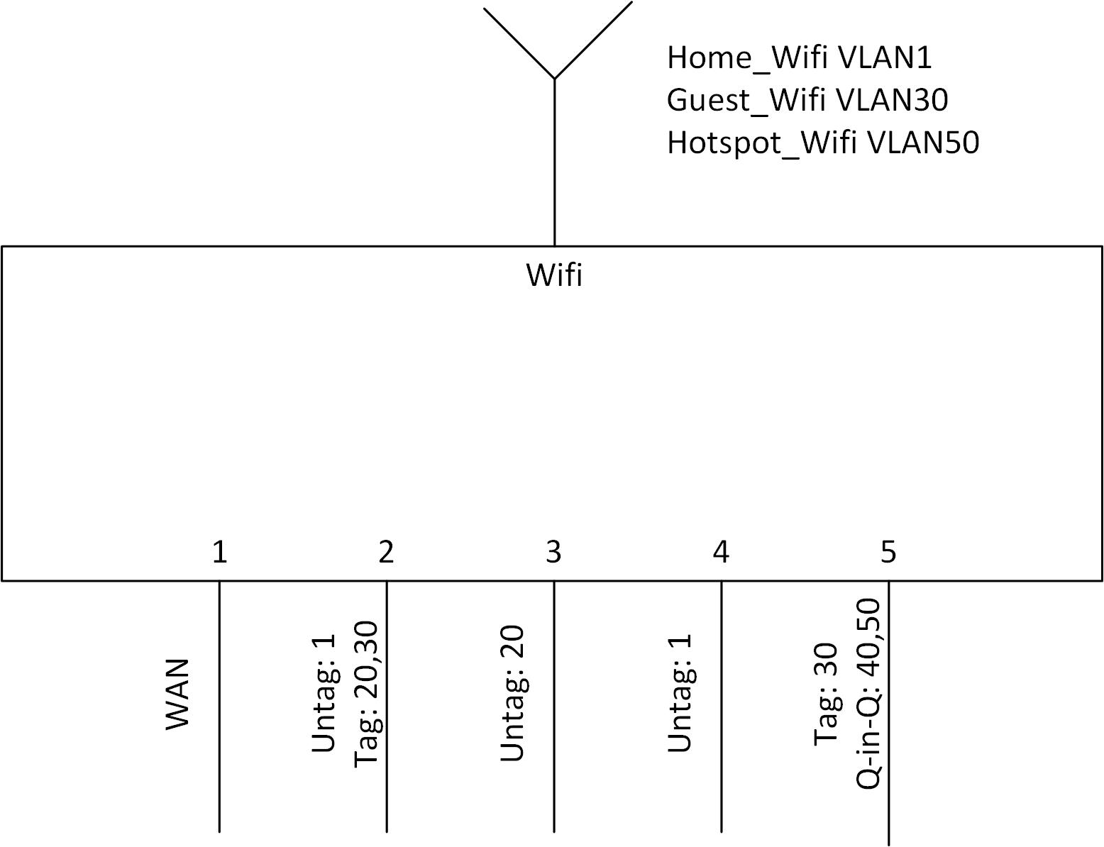
Port:
- WAN
- Trunkport with VLAN 1 as untagged and VLAN 20 and 30 as tagged
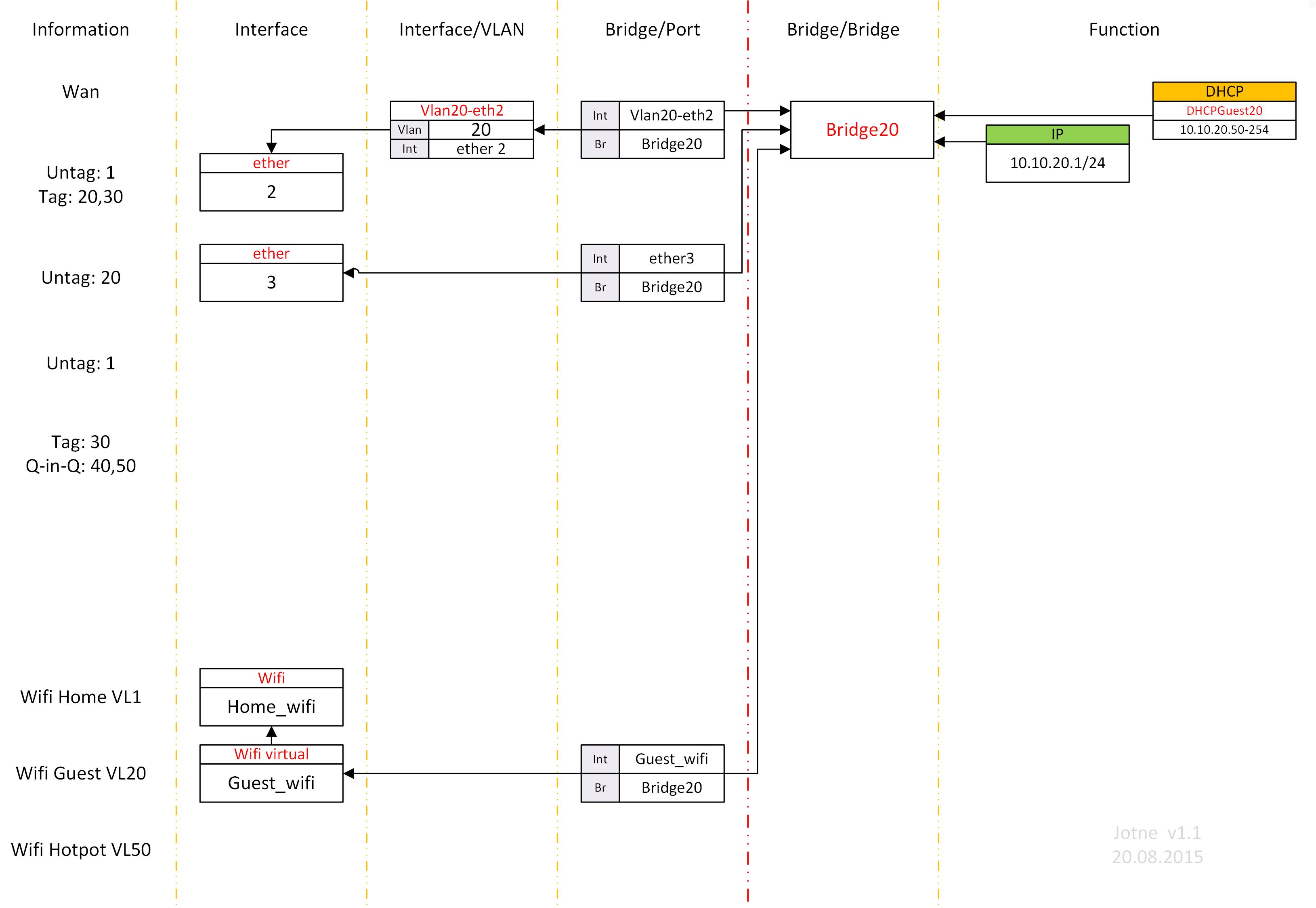
- Untagged VLAN 20
- Untagged VLAN 1
- Q-in-Q VLAN 40 and 50 are transported over tagged VLAN 30
VLAN
- Default home VLAN
- Guest VLAN
- Neighbor VLAN
- Test VLAN
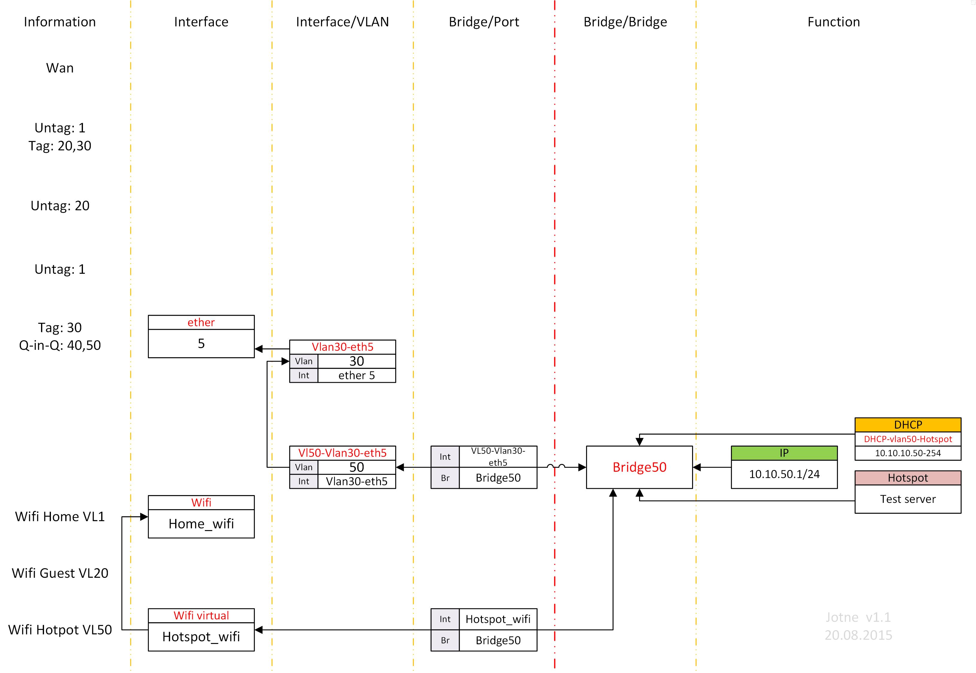
- Hotspot VLAN
WLAN
- Home_Wifi (Home network)
- Guest_Wifi (Guest network)
- Hotspot Wifi (Uses MikroTik hotspot function. User can be on Router, or external Radius server)
It does not explain hotspot, just show how its connected.
RuterOS setup
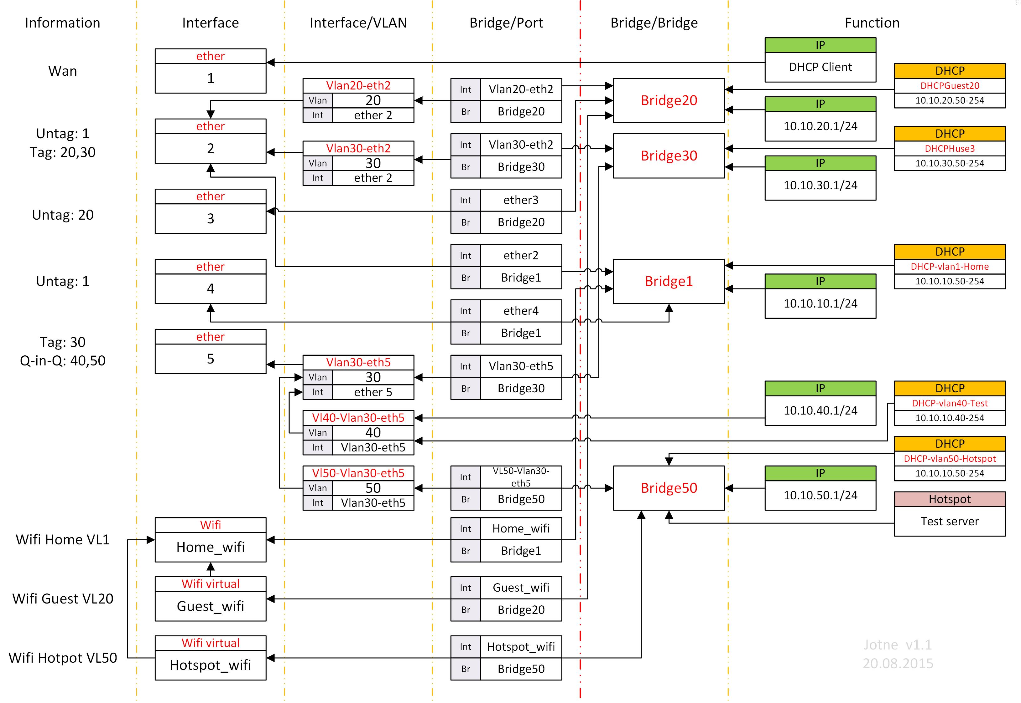
Explanation:
Orange/Red line, separates the different modules used in RouterOS (configure paged)
Red line helps to identify need of Bridge or not.
Information: What is the use on the drawing:
- Interface:
Physical or Virtual interfaces,
Configured GUI: “Interface->Interface” Cli “/interface” - Interface/VLAN
This is where VLAN tag is added/removed. Only need this part if you like a port to send/receive tagged VLAN
Configured GUI: “Interface->VLAN” Cli “/interface vlan”
Connects only to interfaces and other Interface/VLAN (VLAN tag) - Brige/Port
This connects the Interface/VLAN tag to the Bridges
Only needed if Bridge is used.
Configured GUI: “Bridge->Port” Cli “/interface bridge port” (Why this has a different menu structure on GUI vs CLI is some strange. Should be the same)
Connects Interface or Interface/VLAN (VLAN tag) to a Bridge - Bridge
Used as a hub for connecting multiple stuff togeather
Configured GUI: “Bridge” Cli “/interface bridge” (Why this has a different menu structure on GUI vs CLI is some strange. Should be the same)
Connects to norhing - Function
These are various Function used to the network (IP/DHCP/Hotspot)
Connects to Bridge or Interface/VLAN (VLAN tag) or Interface (Physical or Virtual)
Text in red is label used in RouterOS
VLAN are not used inside of the RouterOS in the example, it is just added or removed at the port side.
So you can have many different Bridges or network without using VLAN at all. VLAN are only needed when you like to tag a packed (VLAN tagging)
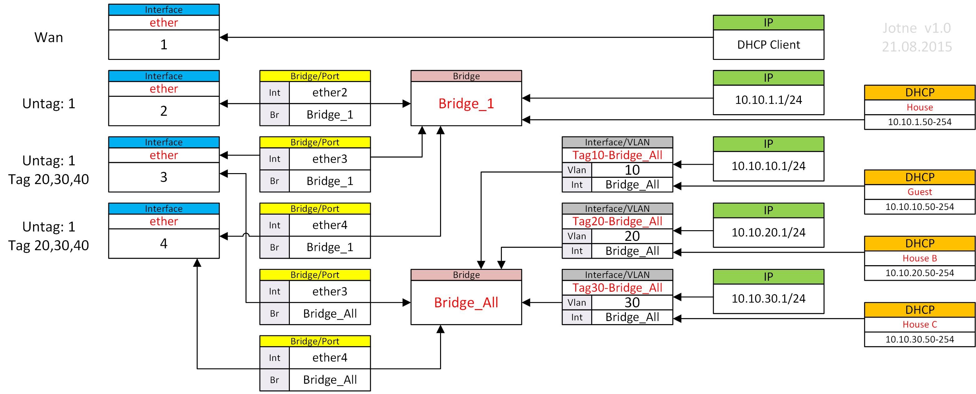
Do I need a Bridge or not?
That depends on the red line.
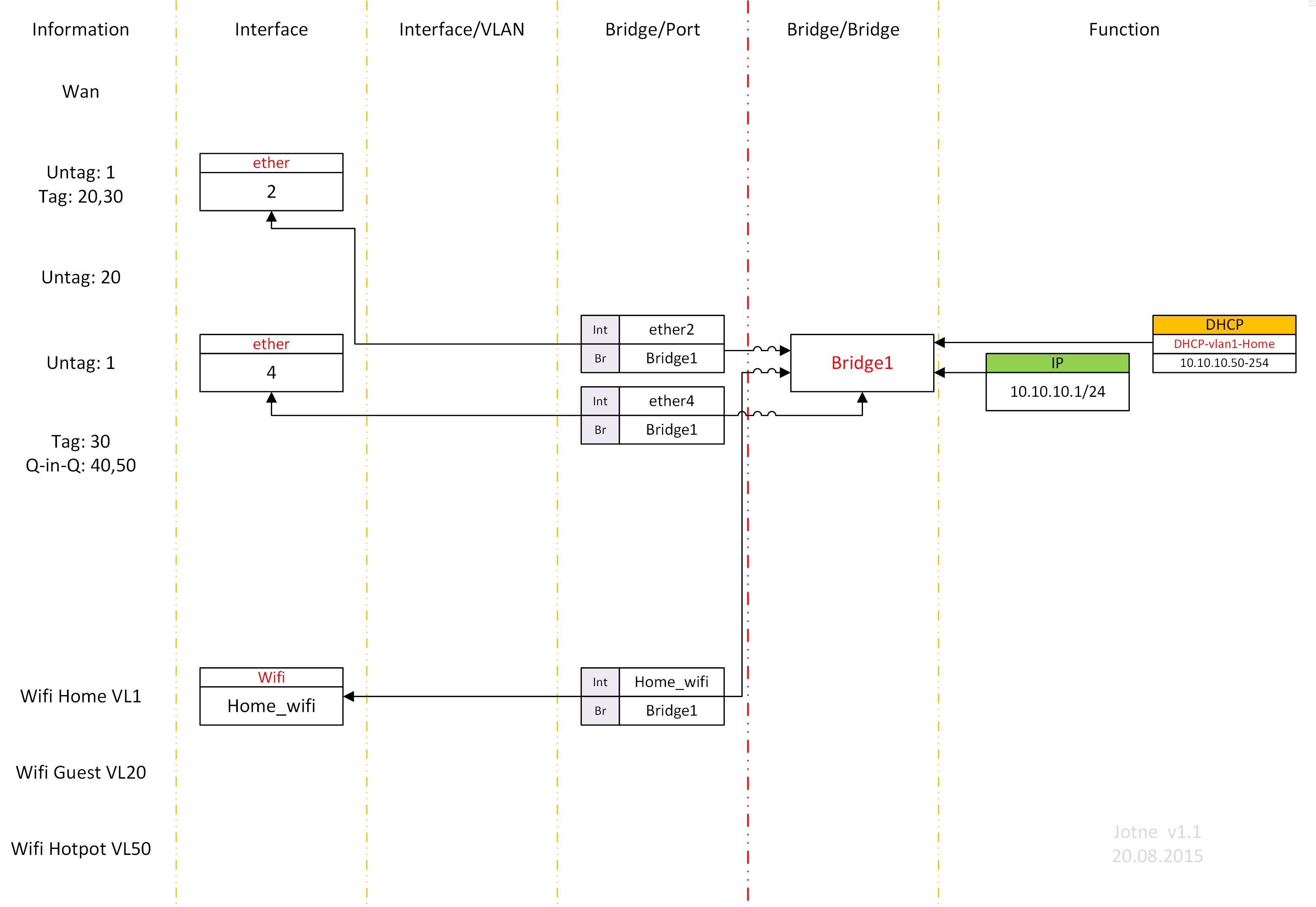
If you have more than one port physical or virtual that will be using the same network, you need a Bridge.
In the example, you have Homnet (1) on Interface 1,4 and Home-Wifi you need a Bridge.
There are more than one interface connecting lines back through red line using same IP/DHCP etc.
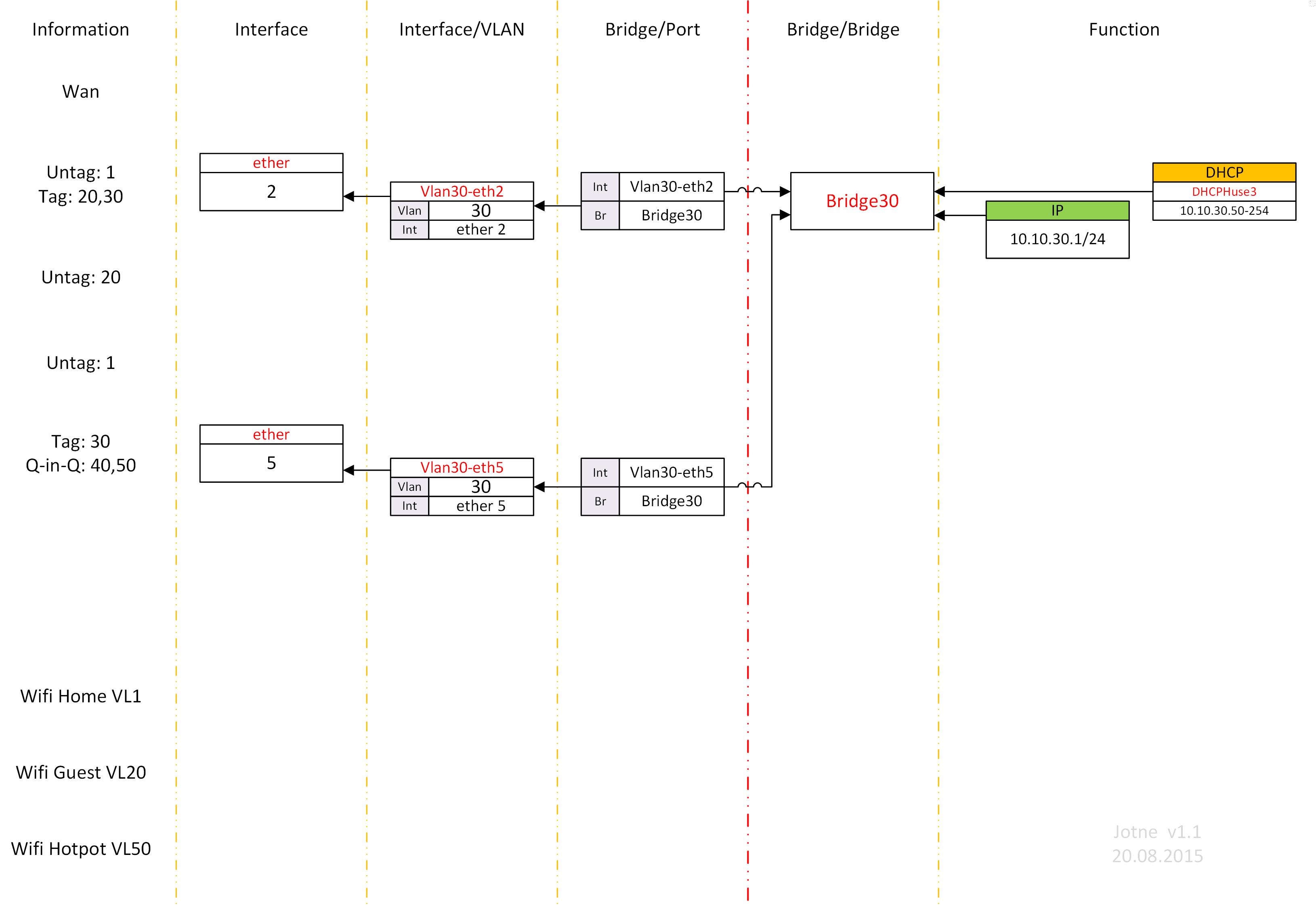
VLAN 40 is only used at port 5 (in a Q-in-Q over VLAN 30) so here is Bridge skipped and IP/DHCP connected to the VLAN tagging of VLAN 40.
If there were a port that do not need VLAN tag, IP/DHCP could be connected all the way to the physical interface.
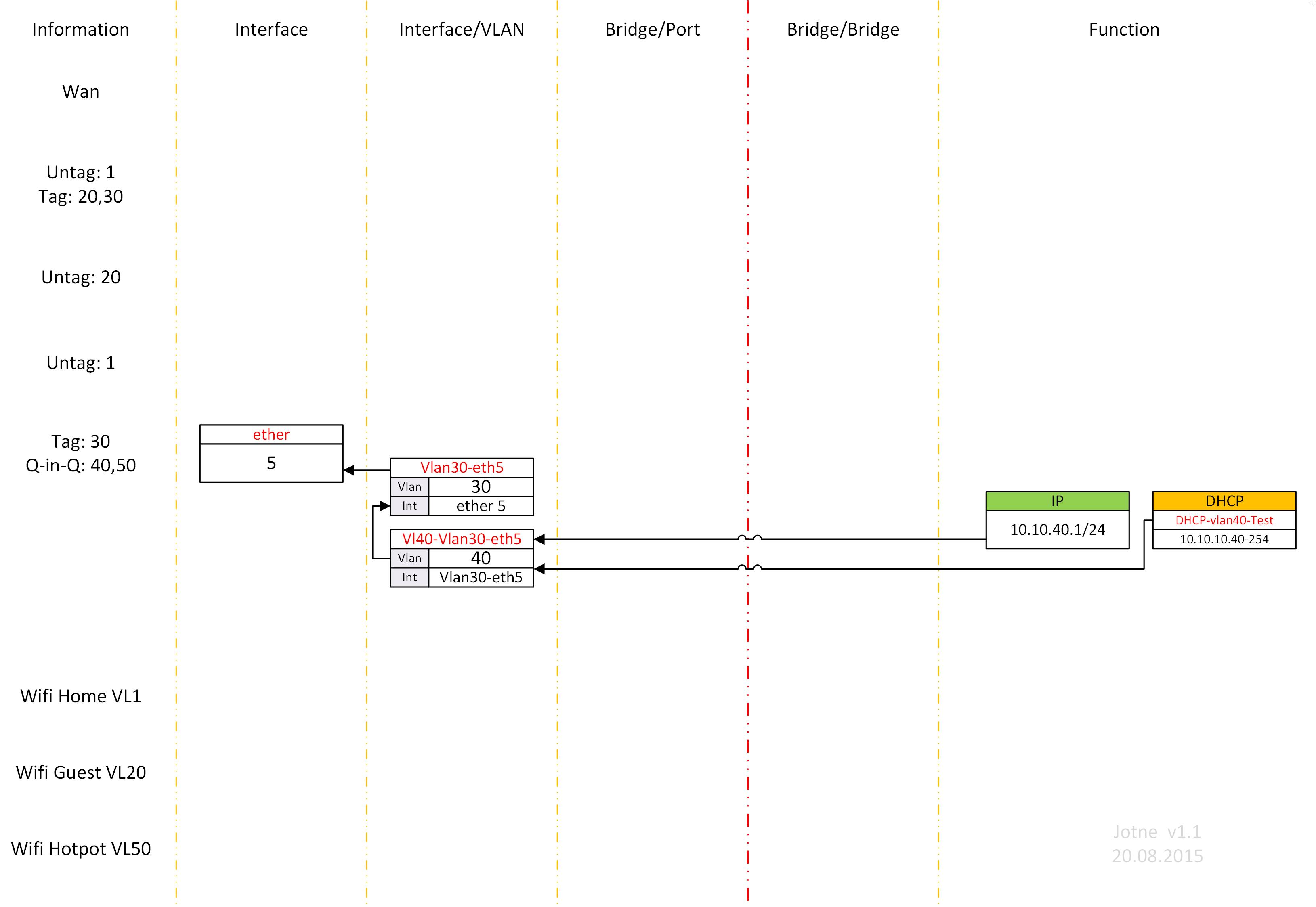
VLAN tagging
VLAN tag are added to each interface that needs it trough (Interface/VLAN)
If you have several interface that need the same VLAN (example 30), you need one Interface/VLAN tagging for each interface.
Q-in-Q
It done the same way as VLAN tagging, but instead of connecting Interface/VLAN to a port, connect it to a Interface/VLAN tagging function.
VLAN tag 40 and 50 are both connected to VLAN tag 30. VLAN tag 30 is connected to Port 5
PS If you do add IP address to a Bridge or Interface/VLAN (VLAN tag) or Interface (Physical or Virtual), you will get routing between this network and other network you have IP on. To prevent traffic from one net to another use firewall rules.
Hopes this helps some to understand VLAN/Bridges in RouterOS.
Look at this from a graphical point is a much better way to do it.