Based on the tunnel idea from this thread, here is a minimal example configuration to access the router services (all listening on main) from another VRF.
This is the whole configuration export of the test installation:
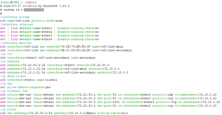
In this test configuration, ether3 has the 172.20.80.2/24 subnet assigned, and is in a VRF named secondary.
/ip vrf
add interfaces=ether3 name=secondary

/ip address
add address=172.20.80.2/24 interface=ether3 network=172.20.80.0
We want the clients connected to ether3 with IP addresses 172.20.80.x, to be able to use the router for DNS, WinBox, and WebFig. All 3 services are by default in the main VRF.
Similar to the other thread:
-
First, add a dummy bridge and two MACVLAN interfaces above it, with mode set to
bridge:/interface bridge add name=vrf-link protocol-mode=none /interface macvlan add interface=vrf-link mode=bridge name=vrf-link-main add interface=vrf-link mode=bridge name=vrf-link-secondary -
Next, make sure
vrf-link-secondaryis added to thesecondaryVRF (easier to do it with WinBox ).
)./ip vrf set [find name=secondary] interfaces=ether3,vrf-link-secondary -
Add IP -> Address entries for the two MACVLAN interface:
/ip address add address=172.18.0.20/24 interface=vrf-link-main network=172.18.0.0 add address=172.18.0.21/24 interface=vrf-link-secondary network=172.18.0.0 -
We can now add the DSTNAT rules for traffic from
172.20.80.x, with the router as destination (172.20.80.2) coming intoether3(which is part of thesecondaryVRF) for DNS, WinBox, WebFig to direct them to172.18.0.20, which is the IP address of the router on the MACVLAN interfacevrf-link-mainin themainVRF:/ip firewall nat add action=dst-nat chain=dstnat dst-address=172.20.80.2 dst-port=53 \ in-interface=ether3 protocol=udp to-addresses=172.18.0.20 add action=dst-nat chain=dstnat dst-address=172.20.80.2 dst-port=53 \ in-interface=ether3 protocol=tcp to-addresses=172.18.0.20 add action=dst-nat chain=dstnat dst-address=172.20.80.2 dst-port=8291 \ in-interface=ether3 protocol=tcp to-addresses=172.18.0.20 add action=dst-nat chain=dstnat dst-address=172.20.80.2 dst-port=80 \ in-interface=ether3 protocol=tcp to-addresses=172.18.0.20 -
After this step, the router's services will be able to receive and process the incoming packets, however, we still need to properly route their responses, by adding a route for destination
172.20.80.0/24(subnet ofether3) inmain:/ip route add dst-address=172.20.80.0/24 gateway=172.18.0.21@main routing-table=mainThe gateway address used is
172.18.0.21, which is the address of the router on thevrf-link-secondaryinterface in thesecondaryVRF.With this setup, a client on
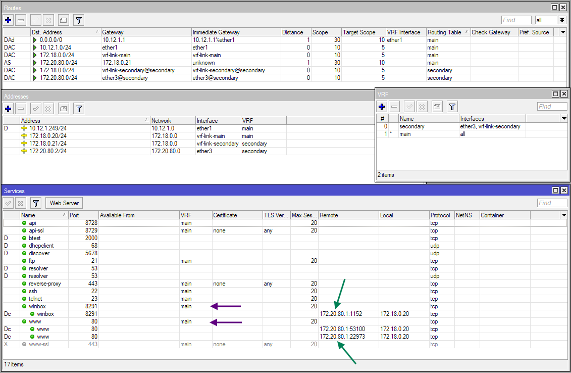
ether3(172.20.80.1in the screenshot below) can access the services without issue:
-
Now if the route at step #5 bother you, and you don't want to leak the route towards
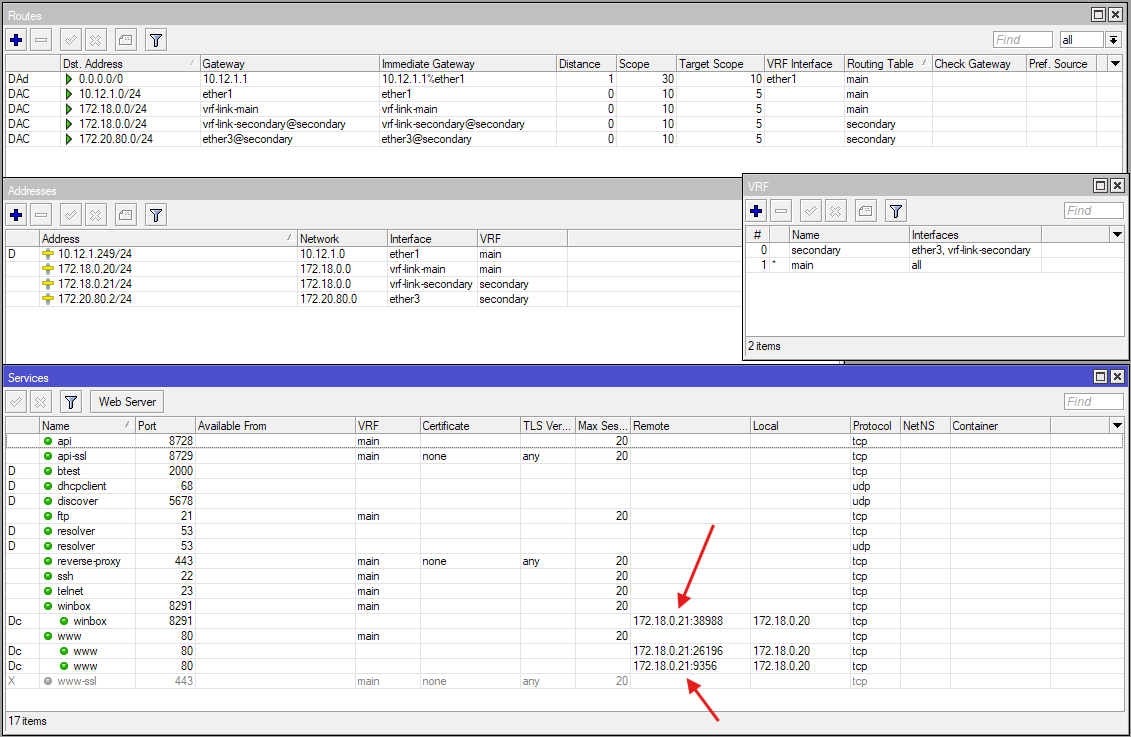
172.20.80.0/24in themainrouting table, then you can remove that route and apply a SRCNAT rule instead:/ip firewall nat add action=src-nat chain=srcnat dst-address=172.18.0.20 \ src-address=172.20.80.0/24 to-addresses=172.18.0.21The downside, however, is that now the source addresses of the clients are masked, and all become
172.18.0.21:
-
If that also bothers you, then you can get rid of the SRCNAT rule, add a new FIB routing table
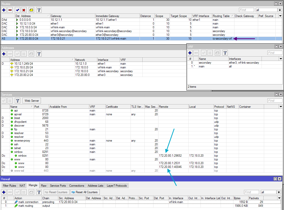
to-secondary-vrfwith the route:/routing table add fib name=to-secondary-vrf /ip route add dst-address=172.20.80.0/24 gateway=172.18.0.21@main routing-table=to-secondary-vrf -
And add mangle
mark-connectionrule to mark incoming connections to172.18.0.20from172.20.80.0/24and correspondingmark-routingrule on theoutputchain for the response:/ip firewall mangle add action=mark-connection chain=prerouting connection-mark=no-mark \ connection-state=new in-interface=vrf-link-main src-address=172.20.80.0/24 add action=mark-routing chain=output connection-mark=from-secondary \ new-routing-mark=to-secondary-vrfWith that, the source IP addresses are retained (no SRCNAT) and there is no route leaking in
mainneeded, only in another routing table (to-secondary-vrf)
You can pick between those three alternatives for step #5 onwards depending on your preference.