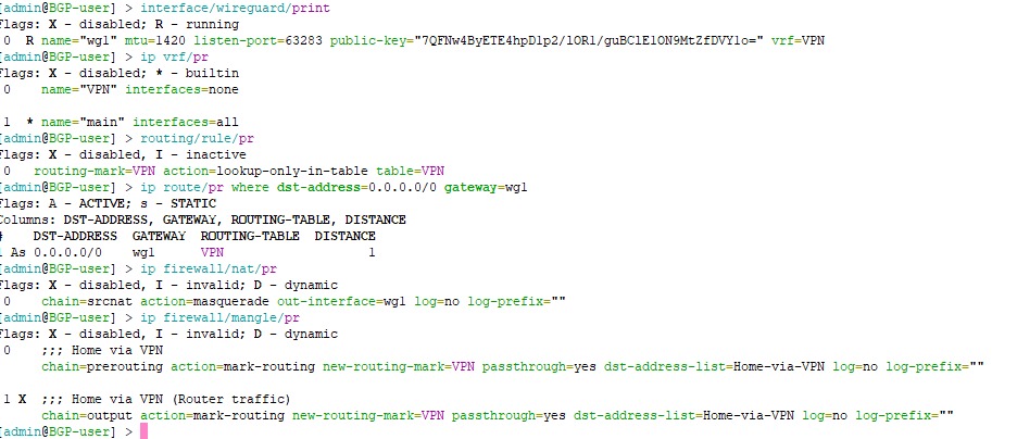
Yes, @lurker888 above has given one example, where all the traffic is to be routed through WG, but the outer WG packets themself, of course need to use the regular WAN.
I have another example for one of the scenarios where this new ability to specify the VRF for WG is very useful, it is when you have multiple WAN, with one let's say WAN1 acting as the main gateway because it has high download bandwidth (1Gbps down, 100Mbps up), but is behind CGNAT with no reachable public IP addresses (and the upload is a bit low), and you have a 2nd WAN with symmetric 250Mbps up/down and public IP address. In this case, this 2nd WAN is ideal to be your WireGuard endpoint to your router (and to reach the LAN network behind it), because of the public IP address and higher upload capacity.
But because WAN1 is our default gateway (and maybe WAN2 is setup as failover) in the main routing table, any attempt to use WG solely on WAN2 would involve another routing table where WAN2 is used as the default gateway.
There were many threads and posts on this forum such as this one Wireguard in 2nd WAN - RouterOS / General - MikroTik community forum or this one WireGuard Multi-WAN Policy Routing - RouterOS / General - MikroTik community forum where people found out that convoluted workarounds (usually DSTNAT and/or SRCNAT together with mangle rules need to be involved) are required if we want WireGuard to answer using any routing table other than main. The added support for VRF with WG in 7.21 will greatly simplify this scenario.
In this example we have two WAN, WAN1 is DHCP client on ether1 and WAN2 is PPPoE client on ether2. Both have dynamic IP addresses, but the one from DHCP is a CGNAT address. The default route from WAN1 is added to main with distance 1, and the default route for WAN2 is added with distance 2.
/ip dhcp-client
add default-route-tables=main interface=ether1

/interface pppoe-client
add add-default-route=yes default-route-distance=2 interface=ether2 \
   name=pppoe-out1 user=... password=....

# configure interface list, input firewall, masquerade etc... if needed
If we now add a WG interface and peers:
/interface wireguard
add listen-port=21204 mtu=1420 name=wg1

# configure address, subnet, and peers
# /ip address add interface=wg1 ...
# /interface wireguard peers add interface=wg1 ...
If we now take our phone and use the WG app on the phone to try to connect to the endpoint specified with the IP address of pppoe-out1 (the address of WAN2), we'll see that the handshake never complete, the app shows Tx bytes being sent, but 0 Rx bytes are received. The reason for this has been explained very well by @lurker888 in the 2 threads I linked above. And you could also employ the workarounds from these threads if you want. But with the VRF support in 7.21 you can do this instead:
-
Create a VRF instance dialup and add pppoe-out1 to it:
/ip vrf
add interfaces=pppoe-out1 name=dialup
We can now see the dynamically added FIB table dialup, and the default route with pppoe-out1 as gateway has been moved to this table, and is no longer in main.
-
Next we set the vrf property of the wg1 WireGuard instance to dialup. I don't know if it's intended by MikroTik or because it's beta, but in my tests I had to disable the wg1 interface first, then set the property, then re-enable wg1 for it to fully work, just setting the property live wasn't enough.
/interface wireguard disable wg1
/interface wireguard set wg1 vrf=dialup
/interface wireguard enable wg1
-
There is no need for extra NAT and mangle rules!
Once this is done, you'll can try with the WG app again and see that connecting to the endpoint using the public IP address of WAN2 now works correctly, as intended.
Moving pppoe-out1 to another VRF however has another important effect. The main VRF now no longer has access to WAN2. In the main routing table there is no more route using pppoe-out1 as gateway, and WAN2 is currently not working as failover anymore.
To have WAN2 as failover again, first we need to "leak" a default route using pppoe-out1 to the main table, with higher distance (because it's failover):
/ip route
add distance=5 dst-address=0.0.0.0/0 gateway=pppoe-out1@dialup routing-table=main
However, if we now unplug the cable from ether1, or disable the DHCP client on ether1 (disable WAN1), so that WAN2 becomes the default route in the main VRF / routing table, we'll notice that while the router itself is still able to go to the internet normally, the clients in our LAN (for example a 192.168.88.6 client on bridge) no longer has internet access, everything times out.
The reason is because although the packets from those clients can successfully be sent out (through the pppoe-out1 gateway) to the internet, any response packets when they arrive to the router, are in the dialup VRF. And in this VRF there are no proper routes to the LAN subnets. There is only one single default route with 0.0.0.0/0 as destination and pppoe-out1 as gateway.
For these packets to be able to be forwarded to the clients, routes must be added to the dialup routing table. We need to "leak" routes for all LAN destinations that we want to be able to use pppoe-out1 as gateway to the internet, the routes would be copies of the ones in main, with @main specified, for example:
/ip route
add dst-address=192.168.88.0/24 gateway=bridge@main routing-table=dialup
add dst-address=10.1.20.0/24 gateway=vlan20@main routing-table=dialup
add dst-address=172.18.4.0/22 gateway=192.168.88.15@main routing-table=dialup
With that the client 192.168.88.6 would have internet connection again, because the return packets know the proper route to use (via bridge interface in VRF main).