Checked that out myself - VLAN filtering comes on an hAP ac² with the cost of increased CPU load (and other devices probably too as only the CRS3xx series supports VLAN filtering in hardware). The other configuration approach is a bit tricky but doesn’t increase CPU load. Here’s a link to my thread for solving this issue successfully: http://forum.mikrotik.com/t/cant-use-vlan-1-as-management-vlan/137678/11
Hi everyone,
I tried to configure my network according to this guideline in the past few days. Everything goes well except for the AccessPoint. I have 7 cAP ac hooked up to the CRS328P and I want to use CAPsMAN on the router to manage all the CAPs. Since the WiFi set up are all configured on the CAPsMAN on the router. I wonder if I need to put the below on the cAP ac. (the wiki guideline seems there is no need to do anything on the AccessPoint itself regarding blue, green, red vlan. https://wiki.mikrotik.com/wiki/Manual:CAPsMAN_with_VLANs).
Thank you in advance !
##################################
egress behavior
/interface bridge vlan
Blue, Green, Red VLAN
add bridge=BR1 untagged=wlan1 vlan-ids=10
add bridge=BR1 untagged=wlan2 vlan-ids=20
add bridge=BR1 untagged=wlan3 vlan-ids=30
egress behavior
/interface bridge vlan
Purple Trunk. L2 switching only, Bridge not needed as tagged member (except BASE_VLAN)
set bridge=BR1 tagged=ether1 [find vlan-ids=10]
set bridge=BR1 tagged=ether1 [find vlan-ids=20]
set bridge=BR1 tagged=ether1 [find vlan-ids=30]
add bridge=BR1 tagged=BR1,ether1 vlan-ids=99
####################################################################
My limited experience goes tgat you have to configure cAPs as far as needed for discovery-interface to have connectivity with capsman. So you need a vlan interface created and L2 config (bridge: ports and vlans) done so that you can configure /interface wireless cap with working discovery-interface …
@mkx , thank you for the input. Yes, I set up the cAP ac so it can find the CAPsMAN, such as discovery interface etc. But I didn’t set up anything regarding blue, red, green vlan. I added the Vlan99 so I can reach the device. Other than that, all configuration regarding vlan was set up in the CAPsMAN on the router according to the wiki. See below my configuration on the cAP ac and the CAPsMAN. I didn’t get it work. Anything I miss ?
@cAP ac
model = RouterBOARD wAP G-5HacT2HnD
/interface bridge
add name=bridge1
/interface wireless
managed by CAPsMAN
channel: 2442/20-Ce/gn(28dBm), SSID: Work, local forwarding
set [ find default-name=wlan1 ] disabled=no ssid=MikroTik
managed by CAPsMAN
channel: 5180/20-Ceee/ac(28dBm), SSID: Guest, local forwarding
/interface vlan
add interface=bridge1 name=vlan99 vlan-id=99
/interface wireless security-profiles
set [ find default=yes ] supplicant-identity=MikroTik
/interface bridge port
add bridge=bridge1 interface=ether1
/interface bridge vlan
add bridge=bridge1 tagged=bridge1,ether1 vlan-ids=99
/interface wireless cap
set bridge=bridge1 discovery-interfaces=bridge1 enabled=yes interfaces=
wlan1,wlan2 static-virtual=yes
/ip dhcp-client
add disabled=no interface=vlan99
/system identity
set name=Test
@ CAPsMAN on the router
[admin@MikroTik] > caps-man configuration print
0 name=“2.4G” mode=ap ssid=“Work” datapath.local-forwarding=yes datapath.vlan-mode=use-tag datapath.vlan-id=10
1 name=“5G” mode=ap ssid=“Guest” datapath.local-forwarding=yes datapath.vlan-mode=use-tag datapath.vlan-id=20
So in capsman one doesnt add the wlans as a bridgeport??
@anav, according to the wiki: “After CAPs are successfully connected to the CAPsMAN Router, the wlan1 (SSID WiFi_WORK) and a newly created virtual wlan5 (SSID WiFi_GUEST) interfaces get dynamically added as bridge ports.” I checked the cAP ac, yes, it is added as shown below. And wlan1 and wlan2 do get the vlan ID of 10 and 20 respectively.
[admin@Test] > interface bridge port pr
Flags: X - disabled, I - inactive, D - dynamic, H - hw-offload
INTERFACE BRIDGE HW PVID PRIORITY PATH-COST INTERNAL-PATH-COST HORIZON
0 ether1 bridge1 yes 1 0x80 10 10 none
1 D wlan2 bridge1 20 0x80 10 10 none
2 D wlan1 bridge1 10 0x80 10 10 none
[admin@Test] >
Yup, capsman does add wlan interfaces as bridge ports with pvid set (if use-vlan=yes on wlan config). But doesn’t take care about trunk ports etc. So you have to configure bridge with vlan-filtering and add all wlan VLANs as tagged to trunk (uplink) port. No need to configure bridge interface as member of those VLANs, bridge will just switch packets, won’t interact with them.
I believe that with datapath.local-forwarding=no none of the above is necessary, I believe in this case all wlan traffic is forwarded to capsman through a tunnel which uses discovery-interface. I’ve never tested such setting, I don’t see it useful in a typical network where L2 is well under control. Plus typically it severely affects wifi performance.
The same what @mkx just wrote but with more details:
cAPsMAN takes care of adding the wireless intefaces to the bridge as /interface bridge port items dynamically, regardless whether datapath.local-forwarding is set to yes or no; with yes, it is the bridge indicated in /interface wireless cap in the cAP’s configuration, whereas with no, it is the bridge on the cAPsMAN machine indicated in the datapath.bridge item:
[me@mycAPsMAN] > caps-man export
…
/caps-man datapath
add local-forwarding=yes name=bridge-test-444 vlan-id=444 vlan-mode=use-tag
add local-forwarding=yes name=bridge-test-777 vlan-id=777 vlan-mode=use-tag
…
/caps-man configuration
add country=“some country” datapath=bridge-test-444 distance=indoors installation=indoor name=my444 security=for444 ssid=ssid444
add country=“some country” datapath=bridge-test-777 distance=indoors installation=indoor name=my777 security=for777 ssid=ssid777
…
/caps-man interface
add configuration=my444 l2mtu=1600 mac-address=66:D1:54:93:A8:5E master-interface=5.master.garage name=5.444.garage radio-mac=00:00:00:00:00:00
add configuration=my777 l2mtu=1600 mac-address=66:D1:54:93:A8:5D master-interface=5.master.garage name=5.777.garage radio-mac=00:00:00:00:00:00
[me@myCAP] > interface bridge port print where bridge=mytestbridge
Flags: X - disabled, I - inactive, D - dynamic, H - hw-offload
INTERFACE BRIDGE HW PVID PRIORITY PATH-COST INTERNAL-PATH-COST HORIZON
0 D wlan630 mytestbridge 444 0x80 10 10 none
1 D wlan631 mytestbridge 777 0x80 10 10 none
It does so regardless whether vlan-filtering on that bridge is set to yes or no. If you set vlan-filtering=yes on the bridge, cAPsMAN will create also the items in /interface bridge vlan:
[me@myCAP] > interface bridge vlan print where bridge=mytestbridge
Flags: X - disabled, D - dynamic
BRIDGE VLAN-IDS CURRENT-TAGGED CURRENT-UNTAGGED
0 D mytestbridge 1 mytestbridge
1 D mytestbridge 777 wlan639
2 D mytestbridge 444 wlan640
However, you have to manually configure items in /interface bridge port and /interface bridge vlan for the ethernet ports so that those VLANs could be connected to other devices via those ethernet port(s):
/interface bridge port
add bridge=mytestbridge interface=ether1(,ether2) (this one is likely there anyway as it is necessary regardless how many VLANs are permitted on ether1)
/interface bridge vlan
add bridge=mytestbridge vlan-ids=444,777 tagged=ether1(,ether2) (plus a separate line for an eventual VLAN-ID you want to have untagged on ether1)
But if the cAPsMAN device is the only one to have an uplink connection to the rest of the network, and if the wireless clients associated to different cAPs do not need to talk to each other directly, there is no real point in using local-forwarding=yes - you may as well let the wireless frames be transported to and from the cAPsMAN machine encapsulated into UDP, and do all the tagging and untagging on the cAPsMAN machine. In such case, you don’t need to bring the VLANs to the cAPs at all.
Should we move the topic to https://forum.mikrotik.com/viewforum.php?f=23 ?
100%!! In a recent survey, 19 Pangolins recommended moving the thread to Useful user articles.
@Sindy, @mkx, thank you for your valuable input. I tried different ways to configure the AP. But still cannot get the WiFi working. Everything else works well.
Therefore, I want to post the configuration for the trial set up. Have been struggling for a week but no success. ![]()
Router: RB951G ( ether1 as WAN, and ether2 as trunk to Switch)
Switch: RB951-2n ( ether1 as trunk to Router, and ether2 to cAP)
AP: wAP (local forwarding mode and controlled by CAPsMAN on Router with 2 SSIDs)
Configuration: according to pcunite’s guideline and wiki: CAPsMAN with Vlan
Issues: Ports of ether 3-5 on router, ether 3-5 on switch works perfect. WiFi doesn’t work, either cannot connect to the SSID or extremely slow.
3/26: I tried in the past few days and herebelow are my observations on the WiFi :
- CAPsMAN with local forwarding mode: Cannot use Vlan filtering on CAP, turn on vlan filtering feature will lose internet connection
- CAPsMAN with manager forwarding mode: very unstable with vlan filtering on, sometimes you can connect to the SSID, sometimes, iPhone is unable to connect to the SSID.
- Most weird thing I noticed, if SSID1 is assigned with vlan10 and SSID2 with vlan20, the SSID1 is always faster and more stable than SSID2. Seems there is a priority. I know there must be something wrong in my configuration but I cannot figure out.
Good day everyone,
I’m new to Mikrotik and very new to VLANs. I have read through a number of posts here and am about to start writing up my own file to implement in my home network. I am still in the learning curve of Mikrotik language so I just wanted to ask about a few of the things stated within the how-tos.
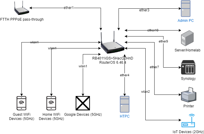
I have a RB4011iGS+5HacQ2HnD so I am trying to implement the method suggested in post #3. While reading through the RouterSwitchAP.rsc, there are a few things I am not sure how to do.
While configuring:
Access Ports: “L3 switching”:
What does it mean to [find vlan-ids=10]?
IP Addressing & Routing: DNS Server:
Do I put my preferred DNS here or do I put 9.9.9.9?
IP Services: /ip dhcp-server network add address=10.0.10.0/24 dns-server=192.168.0.1 gateway=10.0.10.1
How is the dns-server=x.x.0.1? Is this defined somewhere that I missed? I haven’t loaded the RB without default config yet so I am a bit uncertain how this setting works from a fresh start.
This is about as far as I’ve gotten through the file so far before I had enough questions that I feel comfortably lost. Figured I’d post now and get more knowledge before moving forward.
I more than likely will need to post my own topic to get more advice on how to proceed with the way I want my network laid out, but I wan to at least understand this current topic as much as I can before doing so. I’ve attached my network diagram (very skeleton) for ref.
Thank you so much in advance!! I’ve been learning so much already and have mustered enough courage to at least post something here in hopes that you fine folk can lend some expertise.
Yes please take your diagram and post to a new thread and I would like to help after that.
Please share a direct link to the new post then…
I posted a new topic here: http://forum.mikrotik.com/t/new-home-setup-vlans/137961/1
Thanks guys!
Thanks everyone for this great topic! It helped me set up my own network where I have a combined router+switch in one with a trunk port to my VLAN-aware access point. I have two questions I hope you can help me with ![]()
- In my situation, should I have L2 or L3 switch? I.e. should bridge1 be tagged on all VLANs or not? Why?
- How do I know whether I use ‘hardware acceleration’ or not? I’m a bit confused by the many webfig/terminal locations where ‘vlan’ appears.
My setup is as follows:
- VLAN99 is management (172.16.99.0/24), VLAN20 for IoT (no WAN access, only access to server in VLAN99, 172.16.20.0/24), VLAN10 for guest use (only WAN access, 172.16.10.0/24)
- ether1 is used as trunk with VLAN 10 & 20 tagged and VLAN99 untagged for connection to my access point
- ether3 & ether4 are part of VLAN 10, all other ethers are part of VLAN99
- The access point broadcasts one SSID for each VLAN 10, 20, 99
- sfp1 is used for WAN and tagged with VLAN34 (dictated by ISP)
- I’m running an IPSec server (not shown here) serving clients on 172.16.30.0/24, hence for some firewall rules filter on 172.16.0.0/16 to distinguish WAN and VPN traffic
My config:
###############################################################################
Topic: Using RouterOS to VLAN your network
Example: Router-Switch-AP all in one device
Web: > http://forum.mikrotik.com/t/using-routeros-to-vlan-your-network/126489/1
RouterOS: 6.43.12
Date: Mar 28, 2019
Notes: Start with a reset (/system reset-configuration)
Thanks: mkx, sindy
###############################################################################
#######################################
Naming
#######################################
name the device being configured
/system identity set name=“rb2011”
#######################################
VLAN Overview
#######################################
10 = Guest
20 = IoT
99 = BASE (MGMT) VLAN
#######################################
Bridge
#######################################
create one bridge, set VLAN mode off while we configure
/interface bridge add name=bridge1 protocol-mode=none vlan-filtering=no
#######################################
– Access Ports –
#######################################
ingress behavior
/interface bridge port
Purple Trunk to AP. PVID is only needed when combining tagged + untagged
trunk (vs fully tagged), but does not hurt so enable.
add bridge=bridge1 interface=ether1 pvid=99
Guest VLAN
add bridge=bridge1 interface=ether3 pvid=10
add bridge=bridge1 interface=ether4 pvid=10IoT VLAN
BASE_VLAN / Full access
add bridge=bridge1 interface=ether2 pvid=99
add bridge=bridge1 interface=ether5 pvid=99
add bridge=bridge1 interface=ether6 pvid=99
add bridge=bridge1 interface=ether7 pvid=99
add bridge=bridge1 interface=ether8 pvid=99
add bridge=bridge1 interface=ether9 pvid=99
add bridge=bridge1 interface=ether10 pvid=99Tim: WAN VLAN tagging is not set here because it’s not part of bridge
egress behavior
/interface bridge vlan
Guest, IoT, & BASE VLAN + Purple uplink trunk (ether1)
L3 switching so Bridge must be a tagged member
In case of fully tagged trunk, set ether1 to tagged for vlan 99 as well (instead of untagged)
add bridge=bridge1 vlan-ids=10 tagged=bridge1,ether1 untagged=ether3,ether4
add bridge=bridge1 vlan-ids=20 tagged=bridge1,ether1
add bridge=bridge1 vlan-ids=99 tagged=bridge1 untagged=ether1,ether2,ether5,ether6,ether7,ether8,ether9,ether10#######################################
IP Addressing & Routing
#######################################
LAN facing router’s IP address on the BASE_VLAN
/interface vlan add interface=bridge1 name=BASE_VLAN vlan-id=99
/ip address add address=172.16.99.1/24 interface=BASE_VLANDNS server, set to cache for LAN
/ip dns set allow-remote-requests=yes servers=“172.16.99.1”
From > http://forum.mikrotik.com/t/rb951g-2hnd-vlan-tag-on-wan-port/81791/1
/interface vlan add interface=sfp1 name=WAN_VLAN vlan-id=34
Set DHCP WAN client on ether6 AND WAN_VLAN
/ip dhcp-client
add disabled=no interface=WAN_VLAN#######################################
IP Services
#######################################
Guest VLAN interface creation, IP assignment, and DHCP service
/interface vlan add interface=bridge1 name=GUEST_VLAN vlan-id=10
/ip address add interface=GUEST_VLAN address=172.16.10.1/24
/ip pool add name=GUEST_POOL ranges=172.16.10.100-172.16.10.254
/ip dhcp-server add address-pool=GUEST_POOL interface=GUEST_VLAN name=GUEST_DHCP disabled=no
/ip dhcp-server network add address=172.16.10.0/24 dns-server=172.16.99.1 gateway=172.16.10.1IoT VLAN interface creation, IP assignment, and DHCP service
/interface vlan add interface=bridge1 name=IoT_VLAN vlan-id=20
/ip address add interface=IoT_VLAN address=172.16.20.1/24
/ip pool add name=IoT_POOL ranges=172.16.20.100-172.16.20.254
/ip dhcp-server add address-pool=IoT_POOL interface=IoT_VLAN name=IoT_DHCP disabled=no
/ip dhcp-server network add address=172.16.20.0/24 dns-server=172.16.99.1 gateway=172.16.20.1Optional: Create a DHCP instance for BASE_VLAN. Convenience feature for an admin.
/ip pool add name=BASE_POOL ranges=172.16.99.100-172.16.99.254
/ip dhcp-server add address-pool=BASE_POOL interface=BASE_VLAN name=BASE_DHCP disabled=no
/ip dhcp-server network add address=172.16.99.0/24 dns-server=172.16.99.1 gateway=172.16.99.1#######################################
Firewalling & NAT
A good firewall for WAN. Up to you
about how you want LAN to behave.
#######################################
Use MikroTik’s “list” feature for easy rule matchmaking.
/interface list add name=WAN
/interface list add name=VLAN2WAN
/interface list add name=VLAN
/interface list add name=BASE/interface list member
add interface=sfp1 list=WAN
add interface=WAN_VLAN list=WAN
add interface=BASE_VLAN list=VLAN2WAN
add interface=GUEST_VLAN list=VLAN2WANadd interface=IoT_VLAN list=VLAN2BASE
add interface=BASE_VLAN list=BASE
add interface=BASE_VLAN list=VLAN
add interface=GUEST_VLAN list=VLAN
add interface=IoT_VLAN list=VLANVLAN aware firewall. Order is important.
##################
INPUT CHAIN
##################
/ip firewall filter
add chain=input action=accept connection-state=established,related comment=“Allow Estab & Related”Allow BASE_VLAN full access to the device for Winbox, etc.
add chain=input action=accept in-interface-list=BASE comment=“Allow BASE VLAN router access”
Allow IKEv2 VPN server on router
add action=accept chain=input comment=“defconf: accept IKE” dst-port=500,4500 protocol=udp
add action=accept chain=input comment=“defconf: accept ipsec AH” protocol=ipsec-ah
add action=accept chain=input comment=“defconf: accept ipsec ESP” protocol=ipsec-espAllow clients to do DNS, for both TCP and UDP
add chain=input action=accept dst-port=53 src-address=172.16.0.0/16 proto=tcp comment=“Allow all LAN and VPN clients to access DNS”
add chain=input action=accept dst-port=53 src-address=172.16.0.0/16 proto=udp comment=“Allow all LAN and VPN clients to access DNS”add chain=input action=drop comment=“Drop”
##################
FORWARD CHAIN
##################
/ip firewall filter
add chain=forward action=accept connection-state=established,related comment=“Allow Estab & Related”Allow selected VLANs to access the Internet
add chain=forward action=accept connection-state=new in-interface-list=VLAN2WAN out-interface-list=WAN comment=“VLAN Internet Access only”
Allow IoT IoT_VLAN to access server in BASE_VLAN, but no WAN.
add chain=forward action=accept connection-state=new in-interface=IoT_VLAN out-interface=BASE_VLAN dst-address=172.16.99.2 comment=“Allow IoT_VLAN → server in BASE_VLAN”
add chain=forward action=accept connection-state=new in-interface=BASE_VLAN out-interface=IoT_VLAN comment=“Allow all of BASE_VLAN → IoT_VLAN”Allow IPSec traffic from 172.16.30.0/24
add action=accept chain=forward comment=“DEFAULT: Accept In IPsec policy.” ipsec-policy=in,ipsec src-address=172.16.30.0/24
add action=accept chain=forward comment=“DEFAULT: Accept Out IPsec policy.” disabled=yes ipsec-policy=out,ipsecadd chain=forward action=drop comment=“Drop”
##################
NAT
##################
/ip firewall nat
add chain=srcnat action=masquerade out-interface-list=WAN comment=“Default masquerade”
add action=masquerade chain=srcnat comment="Hairpin NAT > https://www.steveocee.co.uk/mikrotik/hairpin-nat/> " dst-address=172.16.99.2 out-interface=BASE_VLAN src-address=172.16.0.0/16##################
Disable unused service ports, whatever this is
##################
/ip firewall service-port
set ftp disabled=yes
set tftp disabled=yes
set irc disabled=yes
set h323 disabled=yes
set sip disabled=yes
set pptp disabled=yes
set udplite disabled=yes
set sctp disabled=yes#######################################
VLAN Security
#######################################
Only allow ingress packets without tags on Access Ports
/interface bridge port
Only
set bridge=bridge1 ingress-filtering=yes frame-types=admit-only-untagged-and-priority-tagged [find interface=ether2]
set bridge=bridge1 ingress-filtering=yes frame-types=admit-only-untagged-and-priority-tagged [find interface=ether3]
set bridge=bridge1 ingress-filtering=yes frame-types=admit-only-untagged-and-priority-tagged [find interface=ether4]
set bridge=bridge1 ingress-filtering=yes frame-types=admit-only-untagged-and-priority-tagged [find interface=ether5]
set bridge=bridge1 ingress-filtering=yes frame-types=admit-only-untagged-and-priority-tagged [find interface=ether6]
set bridge=bridge1 ingress-filtering=yes frame-types=admit-only-untagged-and-priority-tagged [find interface=ether7]
set bridge=bridge1 ingress-filtering=yes frame-types=admit-only-untagged-and-priority-tagged [find interface=ether8]
set bridge=bridge1 ingress-filtering=yes frame-types=admit-only-untagged-and-priority-tagged [find interface=ether9]
set bridge=bridge1 ingress-filtering=yes frame-types=admit-only-untagged-and-priority-tagged [find interface=ether10]
/interface bridge portFor tagged + untagged trunk (management VLAN being untagged), we allow both type of frames
set bridge=bridge1 ingress-filtering=yes frame-types=admit-all [find interface=ether1]
Only allow tagged packets on WAN port
set bridge=bridge1 ingress-filtering=yes frame-types=admit-only-vlan-tagged [find interface=sfp1]
#######################################
MAC Server settings
#######################################
Ensure only visibility and availability from BASE_VLAN, the MGMT network
/ip neighbor discovery-settings set discover-interface-list=BASE
/tool mac-server mac-winbox set allowed-interface-list=BASE
/tool mac-server set allowed-interface-list=BASE#######################################
Turn on VLAN mode
#######################################
/interface bridge set bridge1 vlan-filtering=yes
If you want assistance start a new thread, diagrams help and your exported config.
@PCUNITE (and/or sob, mkx, xvo ) As for the author of this fantabulous guide, getting some pushback of late on the use of pvid and the associated bridge vlan settings:
“The VLAN configuration is fine. Per my previous posts (and the Mikrotik Wiki) it is not necessary to specify untagged= under /interface bridge vlan as these are dynamically generated from the pvid= settings under /interface bridge port.
You can specify both, but if they do not match it causes wierd connectivity issues - this becomes more likely when you are reconfiguring the VLAN on an access port and change one but not the other.”
Question: I dont question the validity of the statement but personally I think its clearer when configuring and reading to have the bridge vlan settings visible. Is there any downside to RELYING on the dynamically generated settings??
This is why I initially showed pvid getting set to the default of “1”. While is not necessary in practice, I thought it would prevent confusion. When there are to many automatic settings being done for you, I think its hard to show the general VLAN concept as well.
After the student has a good understanding, by all means encourage them to configure using brief one-liners. This article is not for illustrating the shortest or even “best” syntax. Rather, its for showing the “clearest” example of VLAN to someone new to MikroTik. Before one can fly, they must walk first.
I acquiesce to the forum’s desire for the “clearest” way. Perhaps an updated section for shortest way would be in order.
I don’t know about this. I got the new config pretty quickly, so I didn’t explore dead ends much. ![]() But if it breaks something, then RouterOS could at least warn about it (similar to warnings in other places).
But if it breaks something, then RouterOS could at least warn about it (similar to warnings in other places).
In any case, current bridge vlan UI in WinBox could use some improvements. So far my idea was that instead of having to select ports one by one from possibly quite long dropdowns, it would be more admin friendly to list all available ports (perhaps only those that are actually part of current bridge), with simple choice between tagged/untagged/excluded using radio buttons for each of them. But if mismatched pvid doesn’t make sense for any config (I’m not sure, I haven’t tried everything), it could be streamlined even more.
In theory mismatched PVID doesn’t necessarily break things. However, it is odd and good practice is to avoid it.
When I first joined this forum, it was because I was abusing a feature, available in other vendor’s managed switch, and I was asking how to do it in ROS. The feature I was asking about is something that allows mismatched PVID settings (they even have name for it: asymmetric VLAN) and it can be used in similar manner as bridge IP firewall or bridge horizon … to prevent certain devices from being able to talk to each other, while the rest can freely communicate to each other.
Consider this scenario:
- (ordinary) router, connected to port1.
- TV set, allowed only to talk to the rest of LAN, connected to port2
- other LAN devices, allowed to talk all over the place, connected to ports 2-5
With mismatched PVID settings this could be achieved in the following manner:
- configure port1 with PVID 60 and add the same port as untagged member of VIDs 60 and 80
- configure port2 with PVID 70 and add the same port as untagged member of VIDs 70 and 80
- configure ports 3-5 with PVID 80 and add same ports as untagged members of VIDs 60, 70 and 80
Now how does it work?
When TV wants to talk to any other device, it sends untagged packet. Due to PVID setting, switch tags that packet with VID=70 on ingress. Let’s say switch doesn’t know the destination port (yet) and forwards the packet to all ports, members of VLAN 70 … which are (apart from port2) ports 3 to 5. Those ports are configured as untagged members of said VLAN and packet gets untagged on egress. Let’s say that target device is connected to port4. When it responds with untagged packet, that packet gets tagged with VID 80 on ingress and switch forwards it to port2 where it gets untagged on egress.
When TV wants to talk to internet, it sends packet towards router. However, port1 is not member of VLAN 70 and switch doesn’t forward packet there.
It is very awkward way of configuration things, but it can help if router is extremely dumb and switch doesn’t support horizons (or similar feature)… neither is true for Mikrotik gear. It gets complicated with more pairs of devices which must not communicate with each other (adding plenty more VLAN ID into the mix), but it is more flexible than bridge horizon and done by switch chip (hence HW offloaded).
I must admit that I didn’t test it on Mikrotik. I guess it might work with VLANs configured on switch chip and setting independent-learning=no on all involved ports. Quite probably the above described functioning is not possible with bridge vlan-filtering as it uses IVL mode.